
The Controller Board is a very delicate component and should only be handled as described in this article.
Important:
- Always hold the Controller Board by its edges when handling it.
- Only remove the replacement board from its antistatic bag when you are ready to install it.
- Handle leads and connectors with care. Never try to remove a connector by pulling on its wires. Always try to grip the connector during removal.
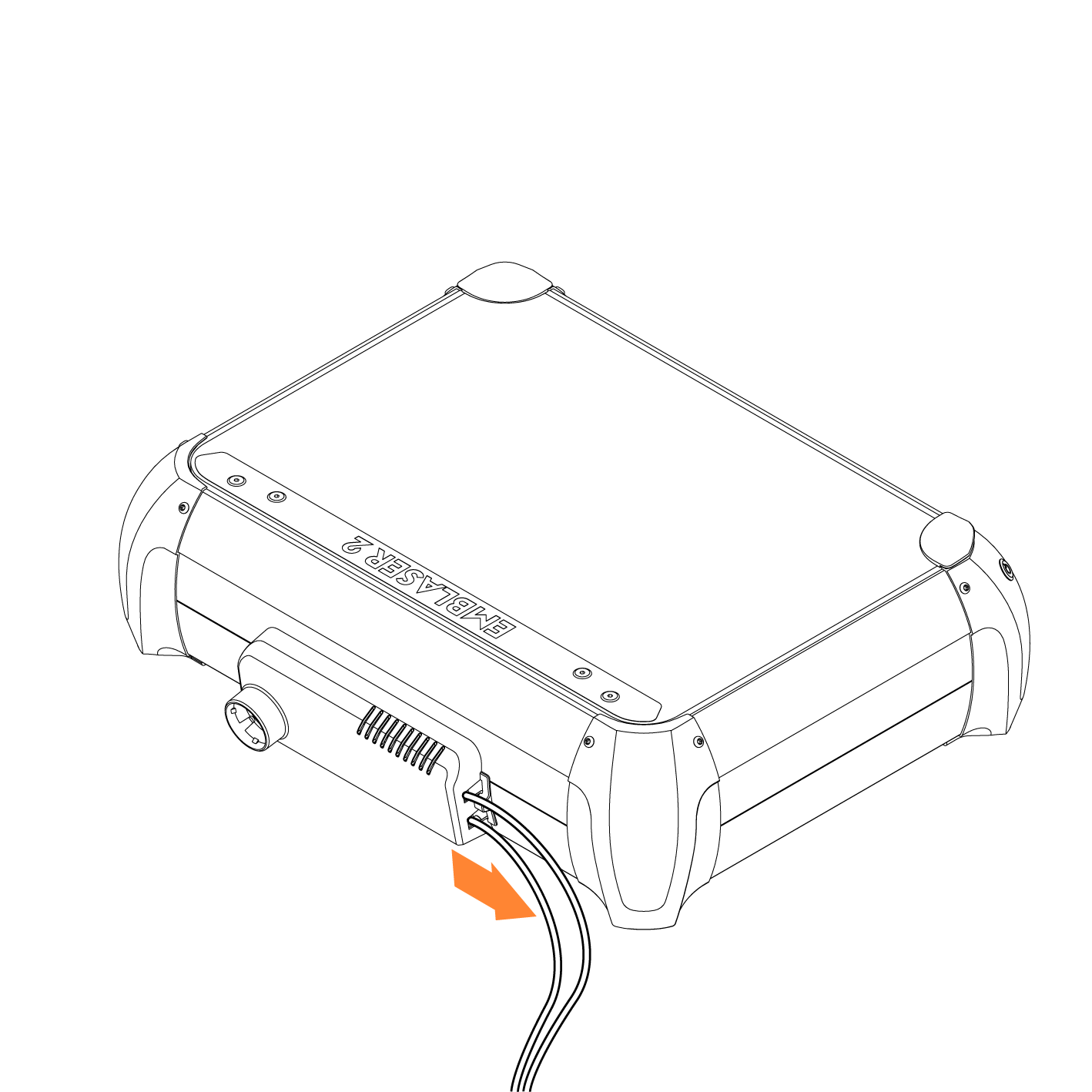
Step 1:
Unplug the USB and power leads from the Emblaser 2.
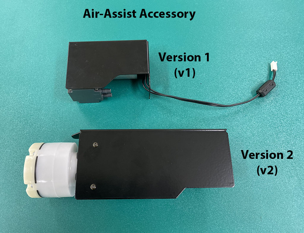
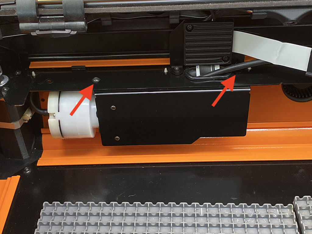
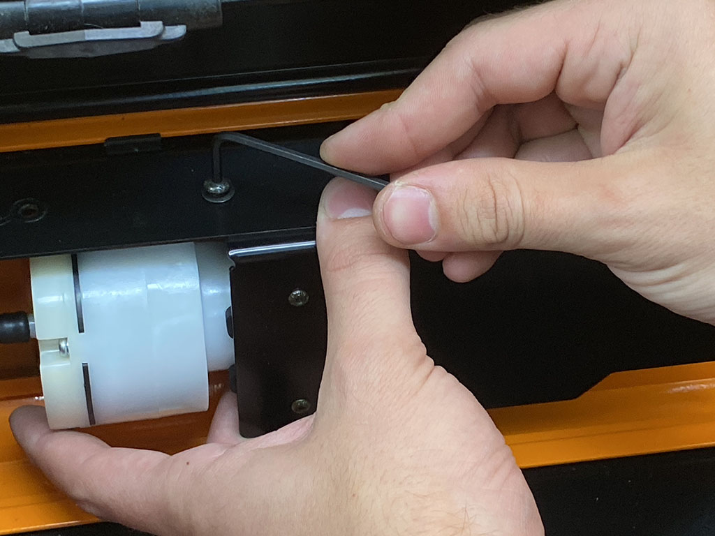
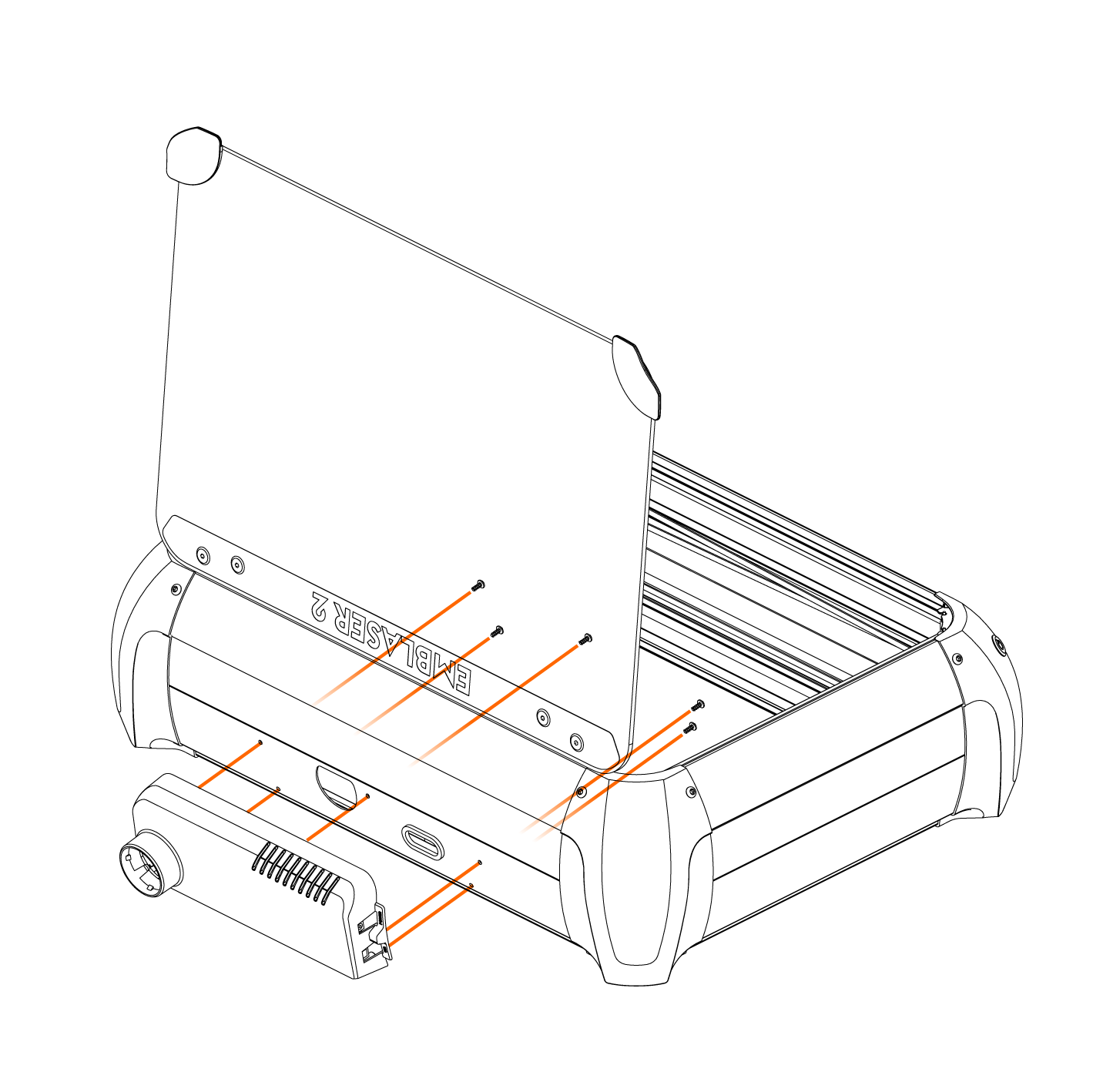
Step 2: (Optional if you have V1 Air-Assist)
If your machine has the new V2 Air-Assist accessory, you will need to detach this before you can access all the screws for the Electronics Pod.
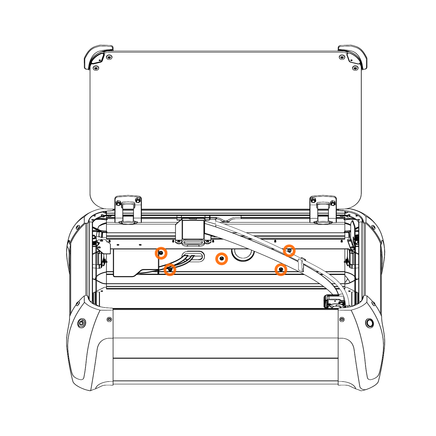
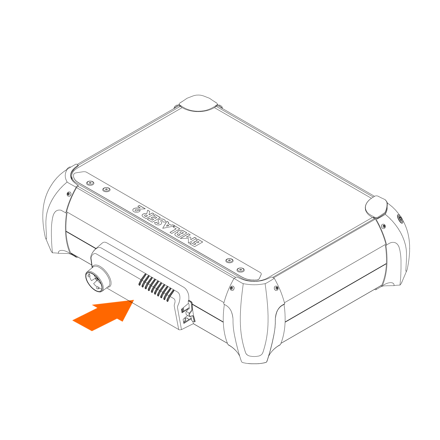
Step 3:
Remove the 5 screws holding the rear Electronics Pod in place
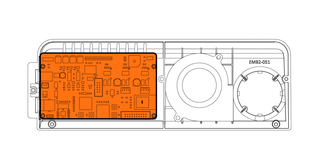
Step 4:
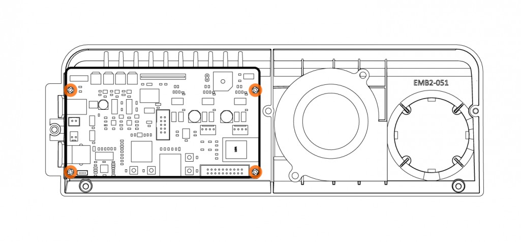
Identify the Controller Board.
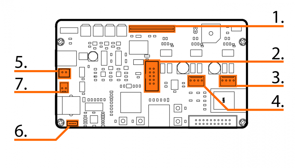
Step 5:
Take note of the connectors and carefully unplug them.
- FFC. Be careful to remove this straight out of the connector, without any twisting.
Refer to this page: Emblaser 2 / Core: Inserting / Removing the FFC (Flat Flexible Cable) - Buttons connector.
- Left motor connector.
- Right motor connector.
- Exhaust fan connector.
- Camera connector.
- Air-Assist connector.
Step 6:
Remove the 4 screws holding the Controller Board in place.
Step 7:
Insert the new Controller Board. Re-insert the connectors and re-attach the Electronics Pod to your machine.
Step 8: (Optional if you have V1 Air-Assist)
Re-attach the Air-Assist accessory.
