
This guide details the process to replace the Potentiometer on an F2000 Fume Extractor.
NOTE: This repair requires some advanced skills, such as soldering and dealing with electrical parts.
If you are not comfortable performing this repair, please consult Darkly Labs for further assistance.
WARNING: Incorrectly performing this repair could permanently damage your F2000 Fume Extractor.
Replacement Parts Required:
- 10K Rotary Potentiometer (Linear)
- Potentiometer Knob (if original is damaged/lost)
- 3 x 10mm (3/8”) lengths of 2mm (1/16”) Heatshrink
- Electrical solder
Tools Required:
- Soldering iron
Step 1:
Unplug the F2000 from the power outlet, then remove the Filters from the top of the unit.
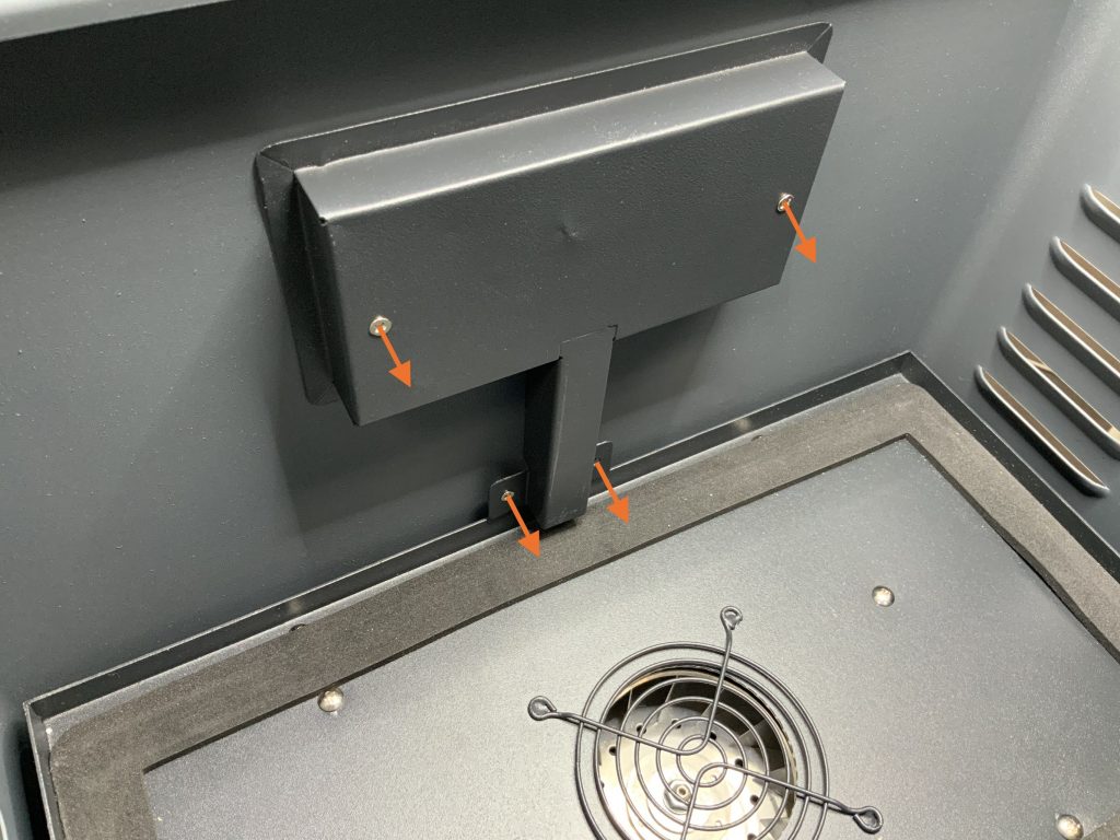
Step 2:
Inside the F2000 there are four screws securing the cover to the side of the unit. Remove all four screw and the Cover, allowing access to the back of the Potentiometer.
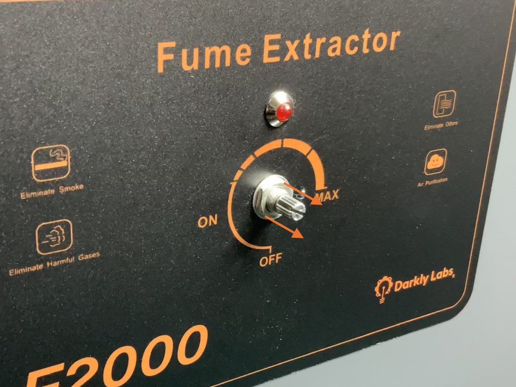
Step 3:
If required, carefully remove the Potentiometer Knob from the front face of the unit.
You should be able to remove this by hand, though you can also use a plastic tool to apply force underneath the Knob if required.
Following this, remove the Nut securing the Potentiometer in place.
Step 4:
From the inside of the F2000, the Potentiometer should now be free to remove.
You may also need to remove the Indicator LED also to allow better access to the Potentiometer, which on most units, is glued in place from inside the machine.
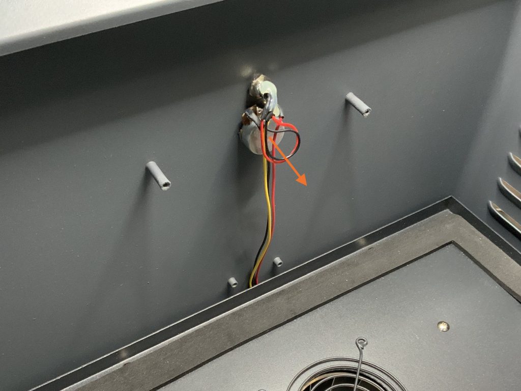
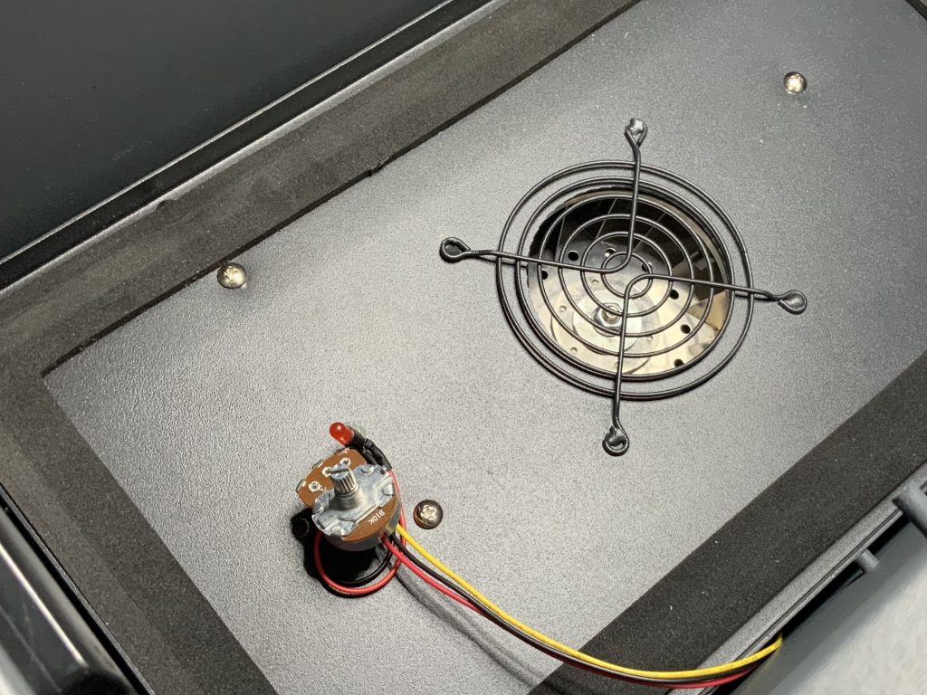
Step 5:
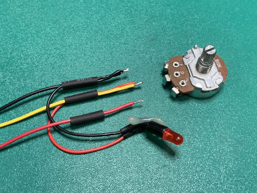
Working inside the filter area, remove the heatshrink from the Potentiometer then desolder the wires.
Slide new heatshrink on the wires as shown below, being sure it is far enough away from the ends not to be effected by heat from soldering.
Note: For the following steps, the Potentiometer has been removed from the F2000 for documentation purposes – these steps can be performed inside the filter area.
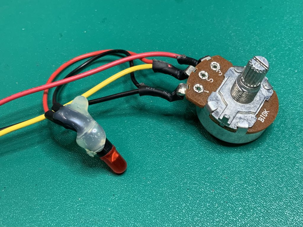
Step 6:
Solder the wires onto the tabs of the new 10K Potentiometer, then slide the heatshrink over the connections and apply heat to shrink them.
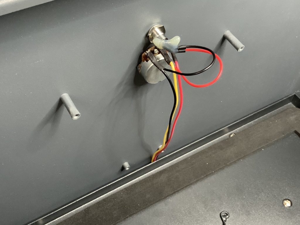
Step 7:
Return the Potentiometer to it’s position within the F2000 and reinstall the Indicator LED if required. Then install the Cover, ensuring the wires are within the four mounting posts:
Step 8:
Replace the Cover then reinstall the Filters inside the F2000.
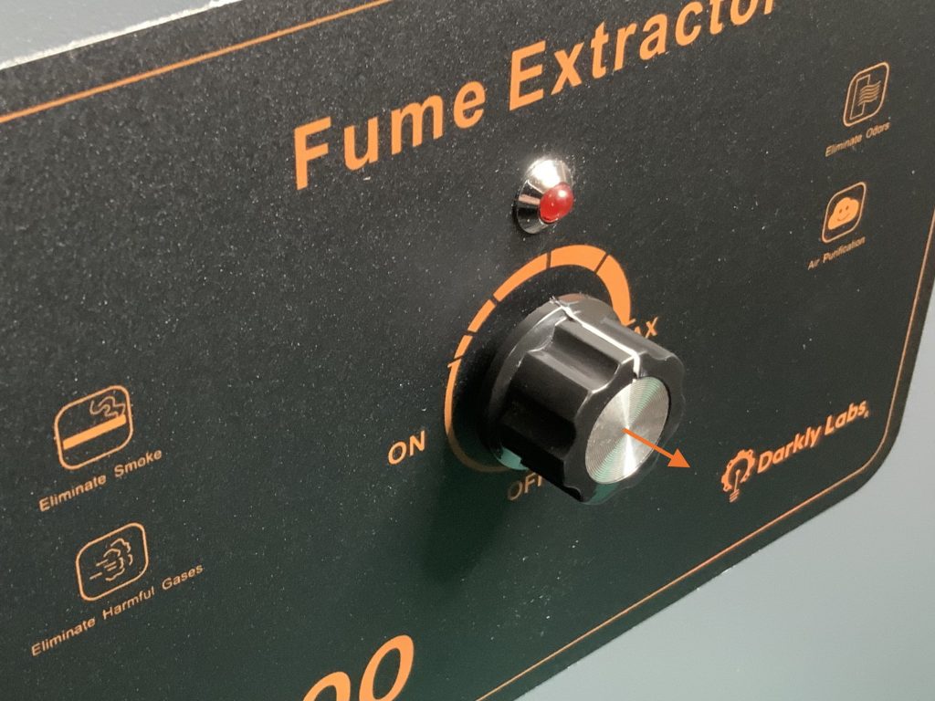
Step 9:
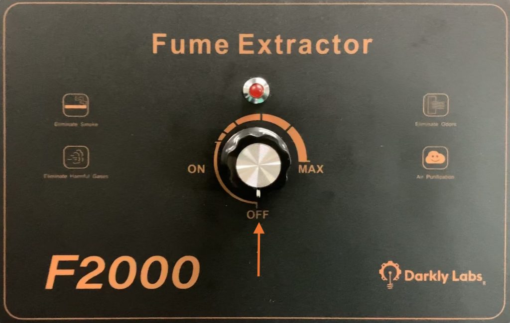
On the front of the unit, turn the Potentiometer Shaft anti-clockwise to the rotation limit and reinstall the Potentiometer Knob with the indicator mark pointing to the OFF position.
Step 10:
Plug in the F2000 and check that it is functioning correctly.
