This article shows how to replace the Controller board for an Emblaser Pro.
IMPORTANT: We classify this process and Medium to Advanced. There are delicate components and connectors on the controller board that need to be handled very carefully.
IMPORTANT: The electronics on the controller board are sensitive to static damage. When performing this process, set up in an area where you can sit comfortably and place parts within hands reach. Do not pick up electronics and walk around with them or pass them from person to person.
IMPORTANT: Be very careful with all connectors, especially the FFC clips. They are very delicate.
Safety
Before opening any panels or performing any work on your Emblaser Pro, ensure it is unplugged from the mains power.
Removing Controller Board
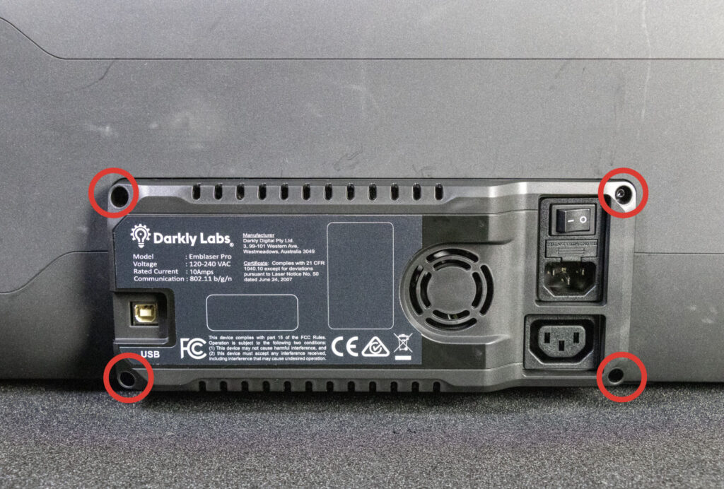
Step 1: Remove the Electronics Cover
Using a Torx T10 screwdriver, remove the 4 screws holding the rear electronics cover in place.
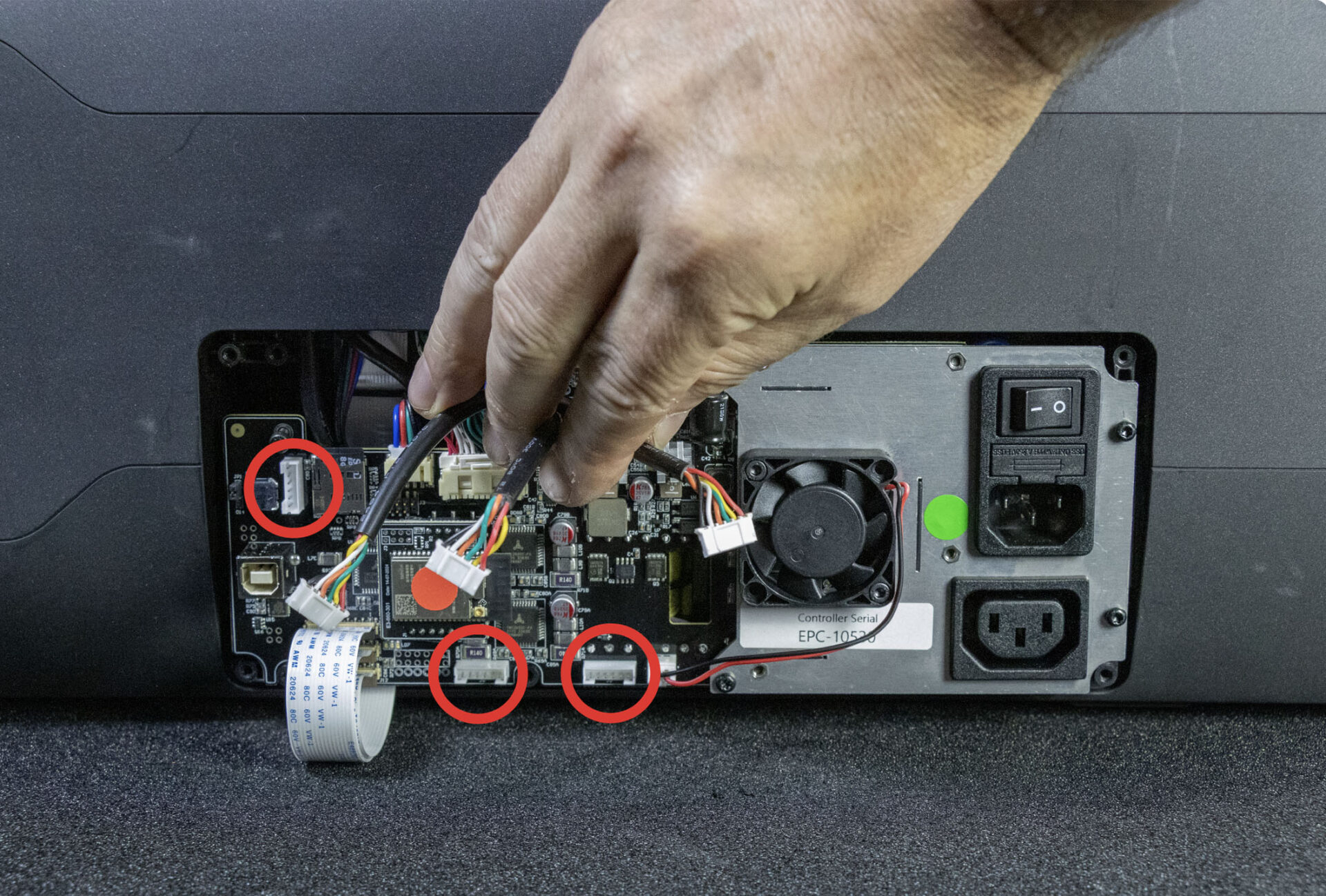
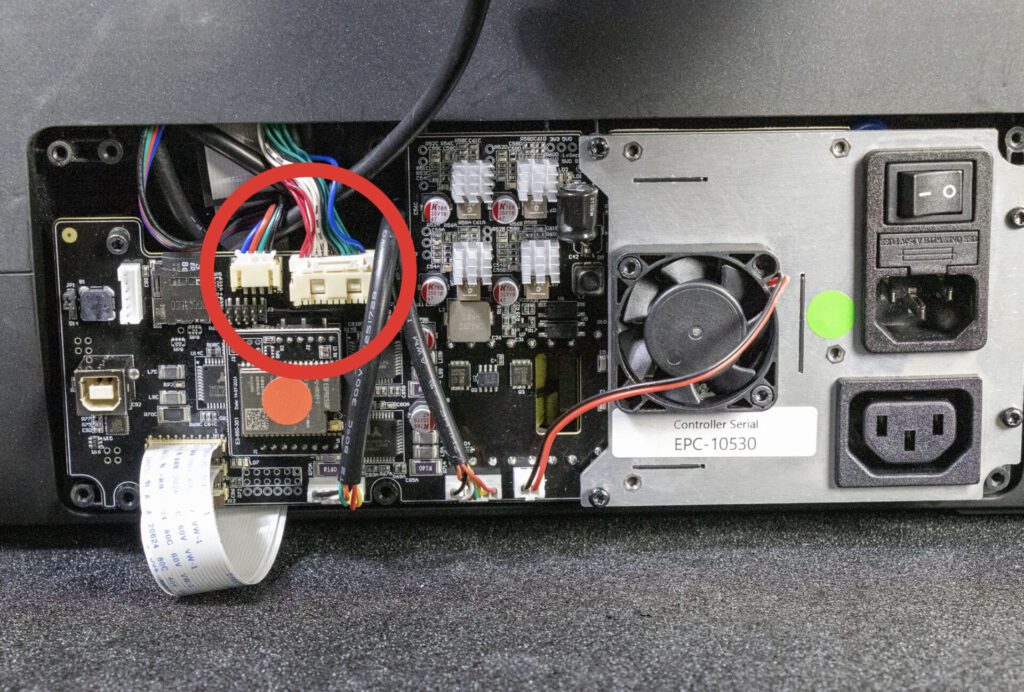
Connector Names
IMPORTANT: Some connectors are delicate. Please take your time and be gentle when plugging and unplugging connectors. If you are unsure, please contact help@darklylabs.com.
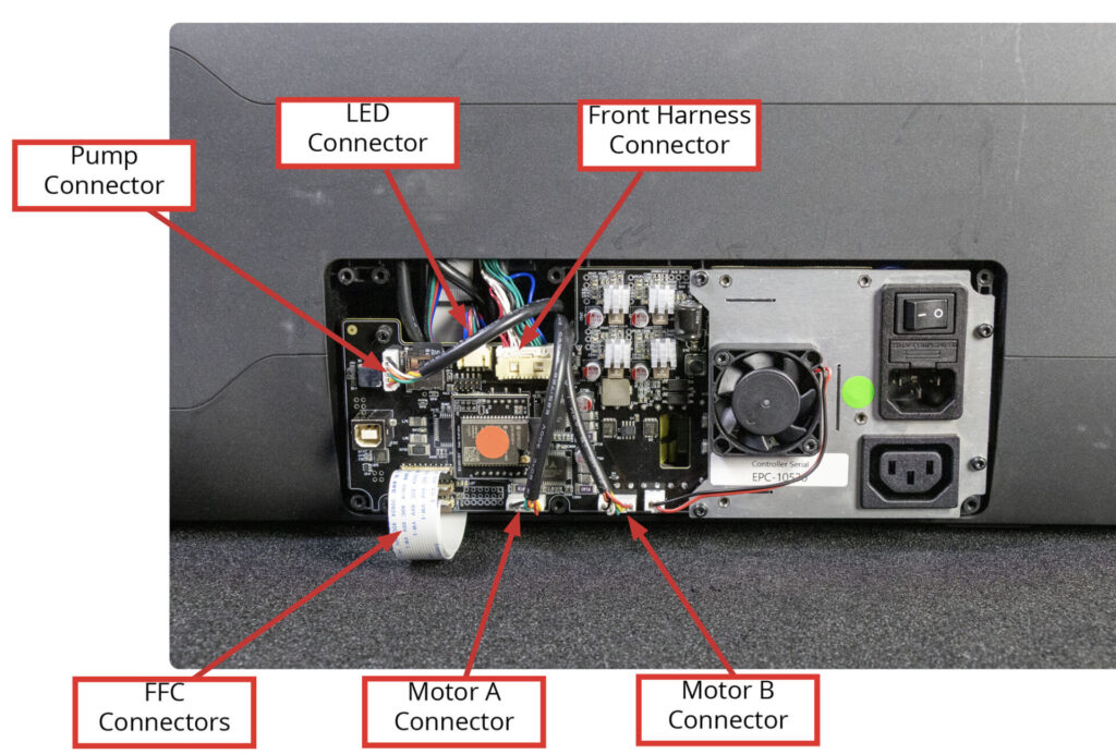
Step 2: Unplug motor and pump cables
Carefully unplug the 2 motor and pump connectors.
Step 3: Unplug Front Harness Connector
Depress clip and pull connector out.
Connector will release and come out.
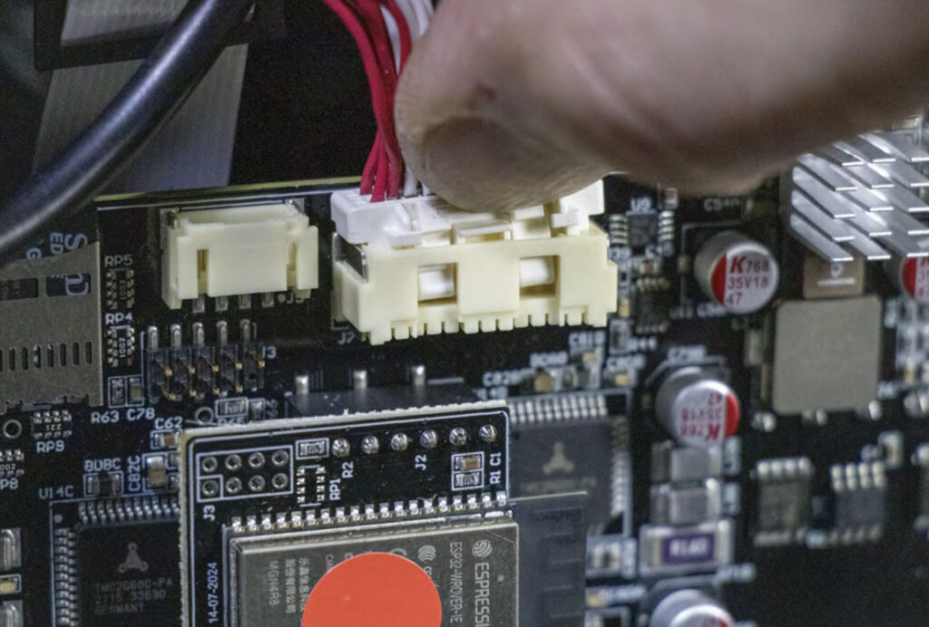
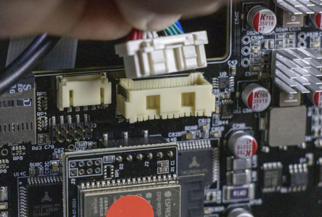
Step 4: Unplug LED Connector
The LED connector will unplug upwards. It may require a little force to remove. Please try not to apply too much force on the wires.
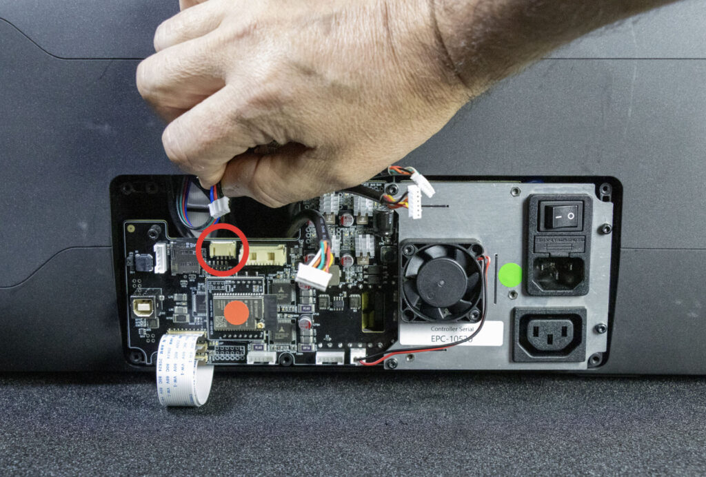
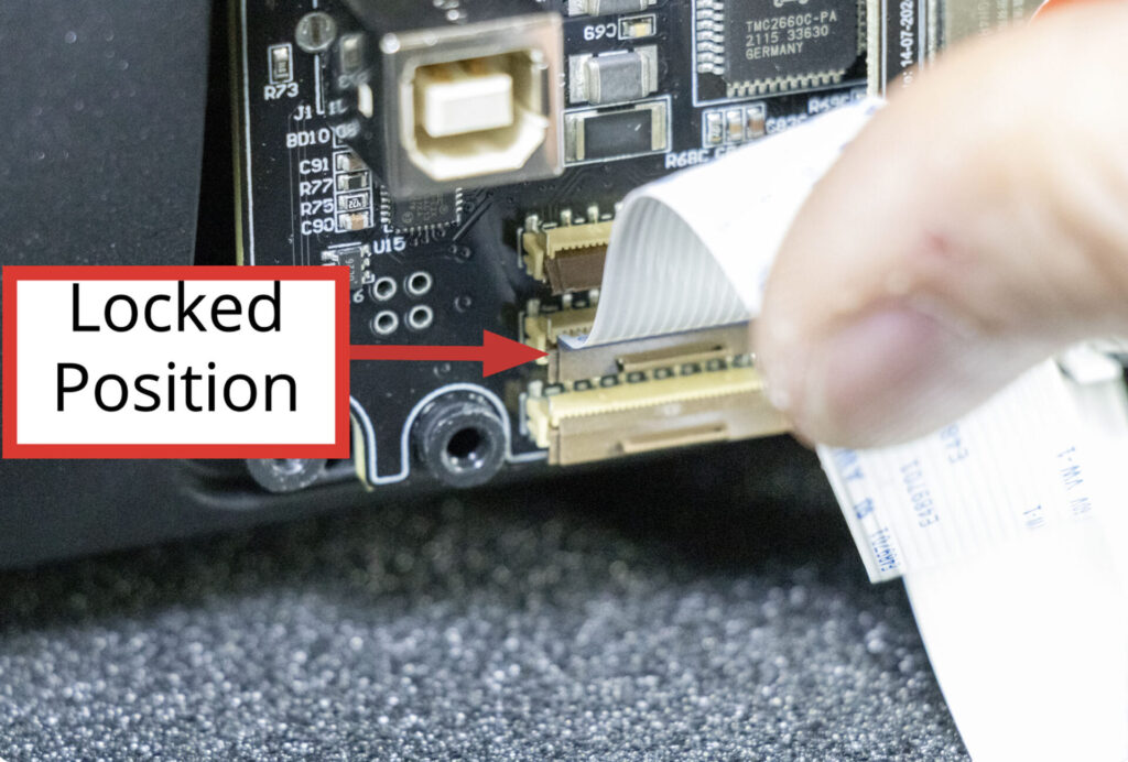
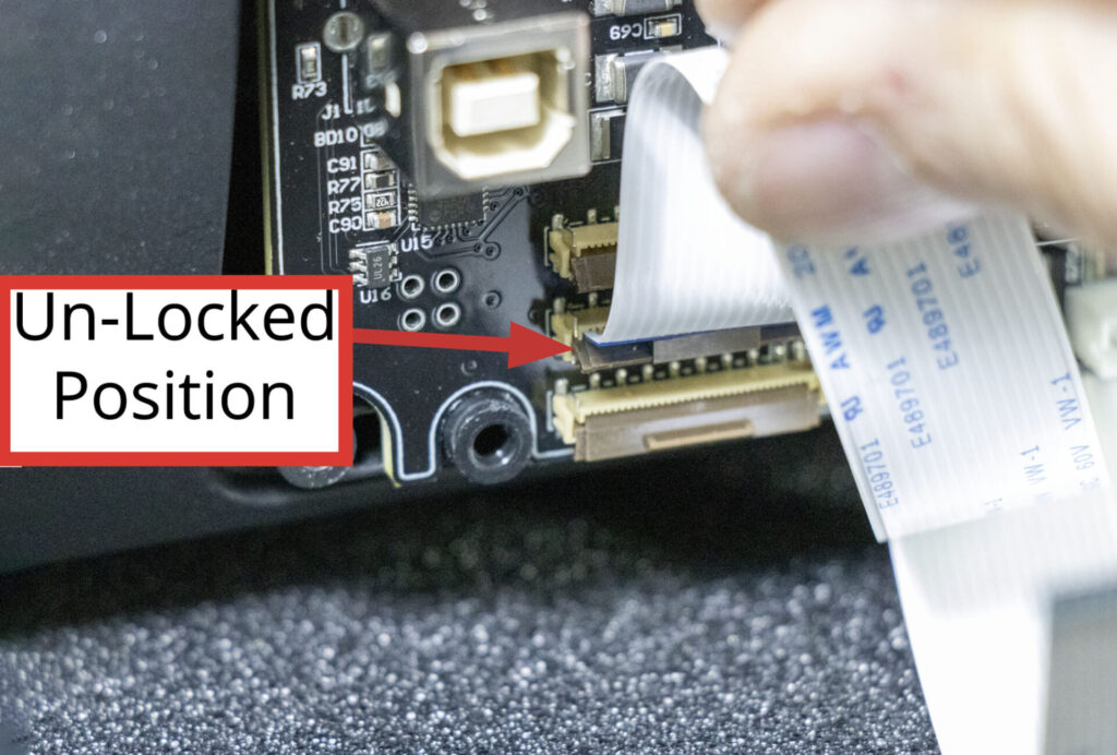
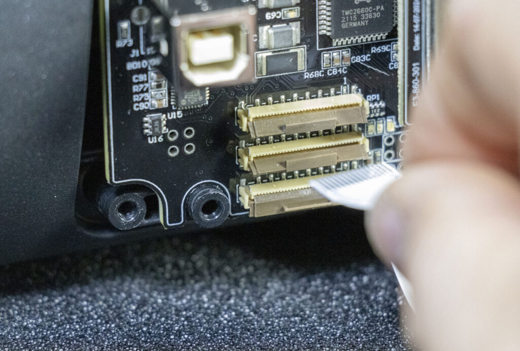
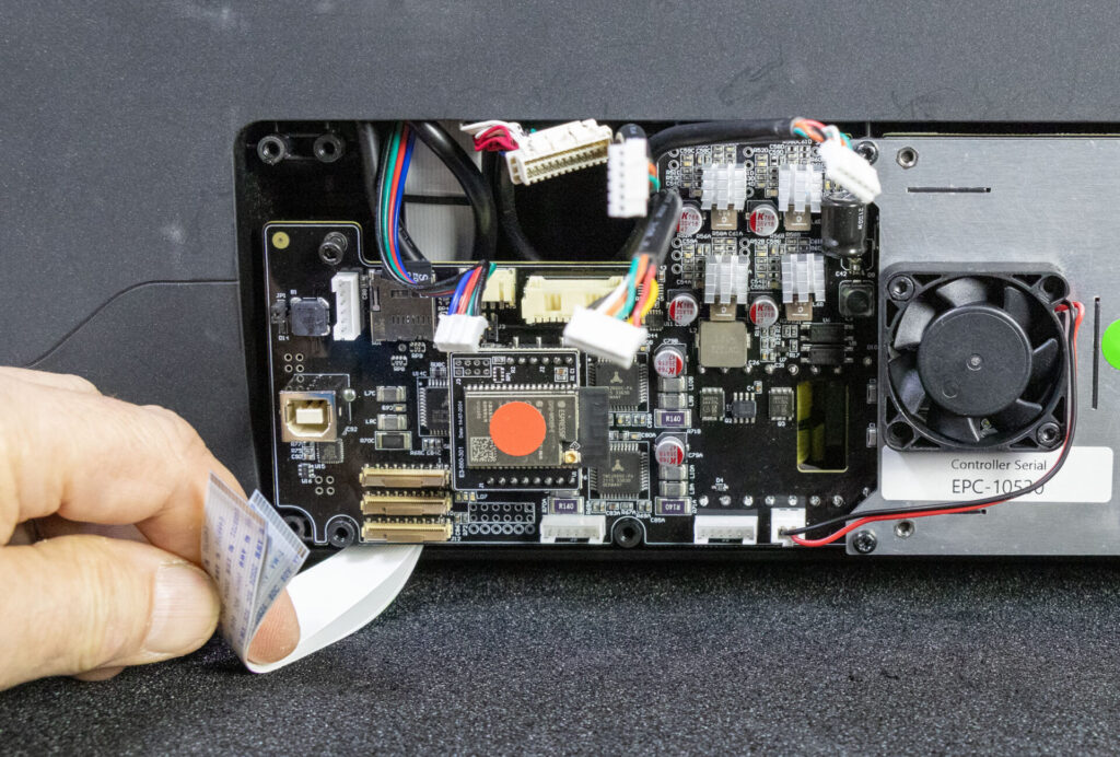
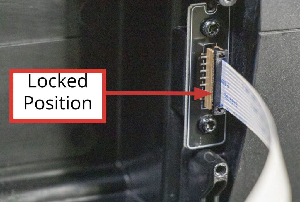
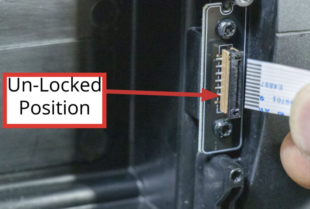
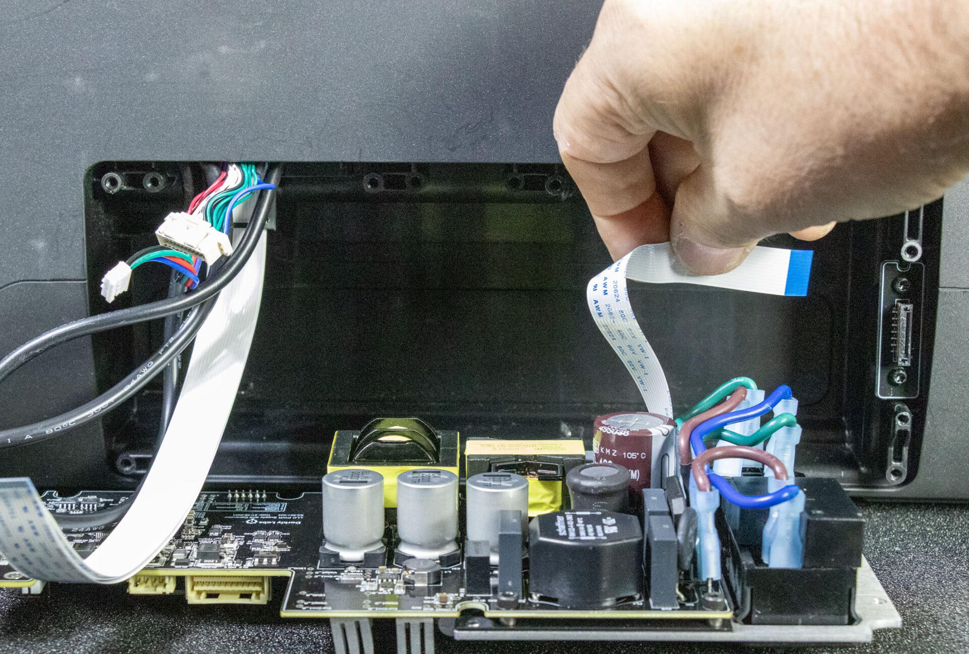
Step 5: Unplugging FFCs
The FFC cables are connected to a locking connector.
Carefully pivot the locking clip upwards to release each of the 3 FFCs
Once released, the FFCs will slide out easily.
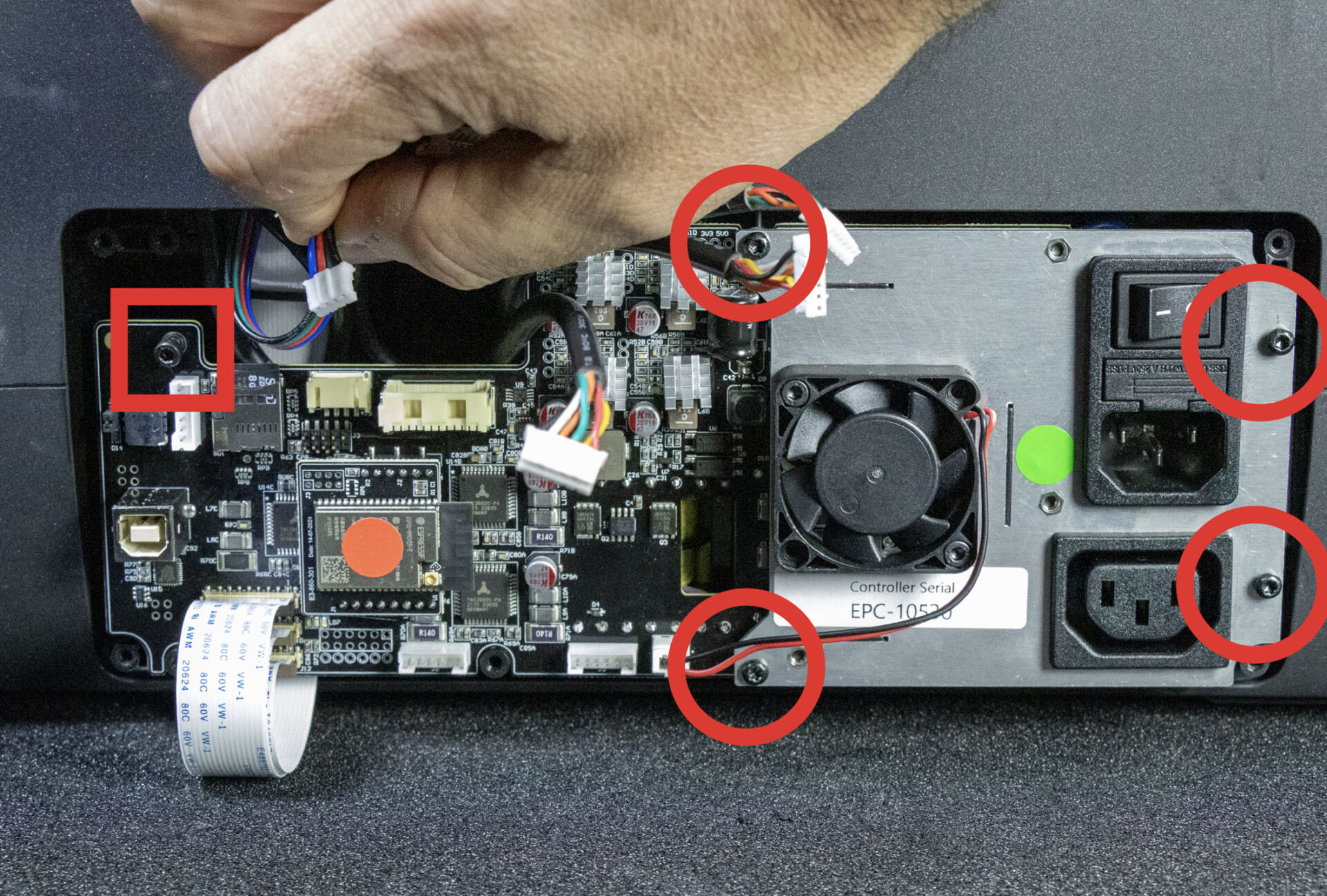
Step 6: Unscrew Controller board
Use your Torx T10 screw driver to remove the 5 screws holding the Controller board in place.
Note that unlike the 4 plastic screws on the right side of the board, the left-most screw is a metal screw and needs to go back in the same position.
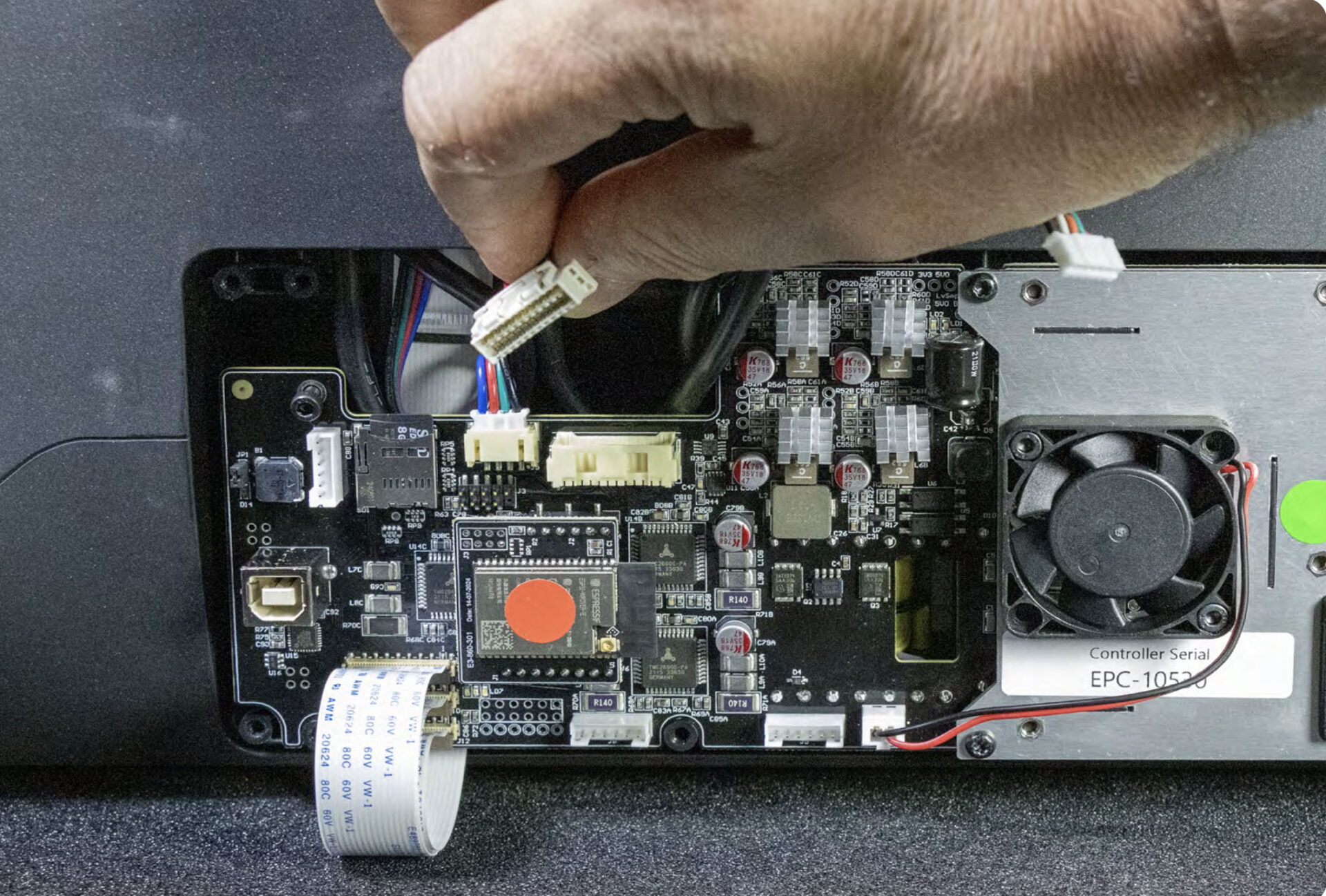
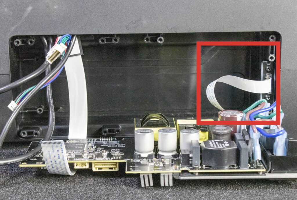
Step 7: Unplug Accessory FFC
Carefully lay the controller board down. Do not pull on it since there is one more cable to unplug. The FFC connector locking clips are quite delicate, so take your time and don’t apply too much force.
The FFC cables are connected to a locking connector.
Carefully pull the black the locking clip outwards to release the FFC.
Installing the new Controller board
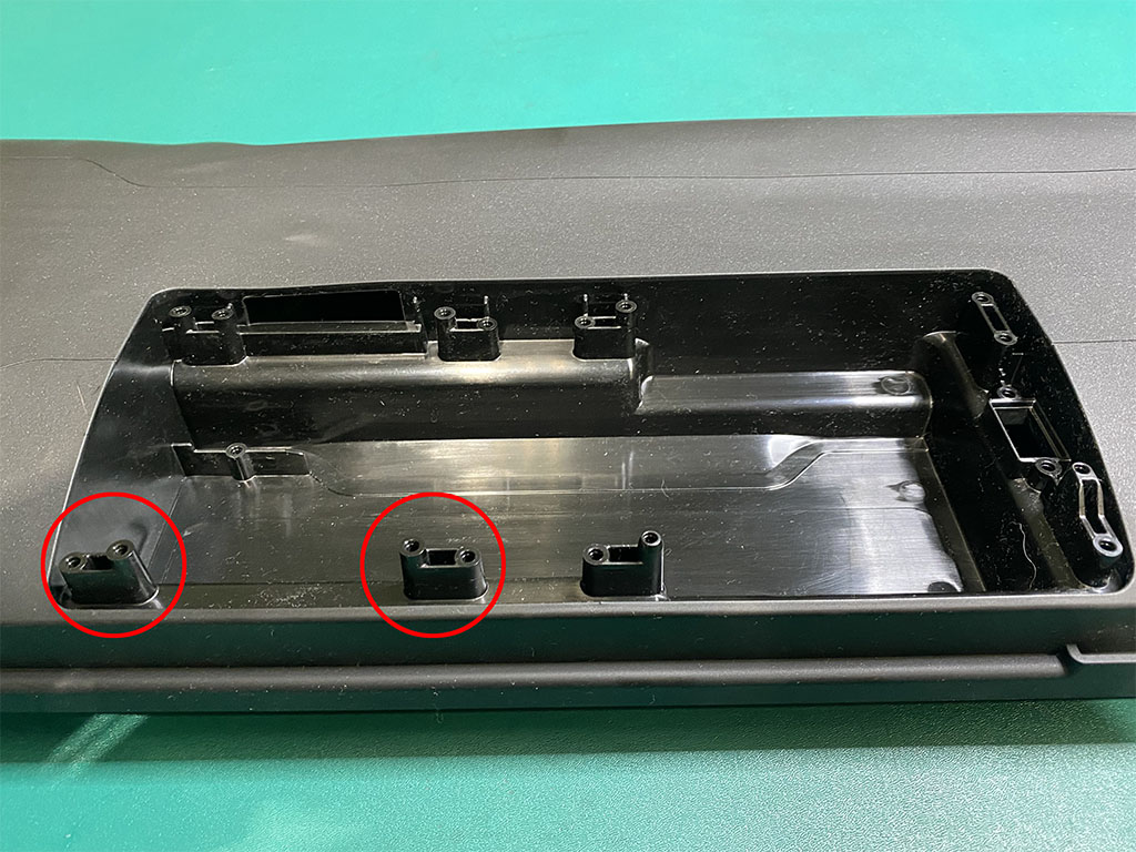
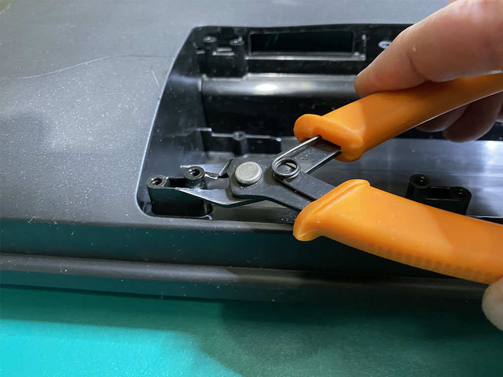
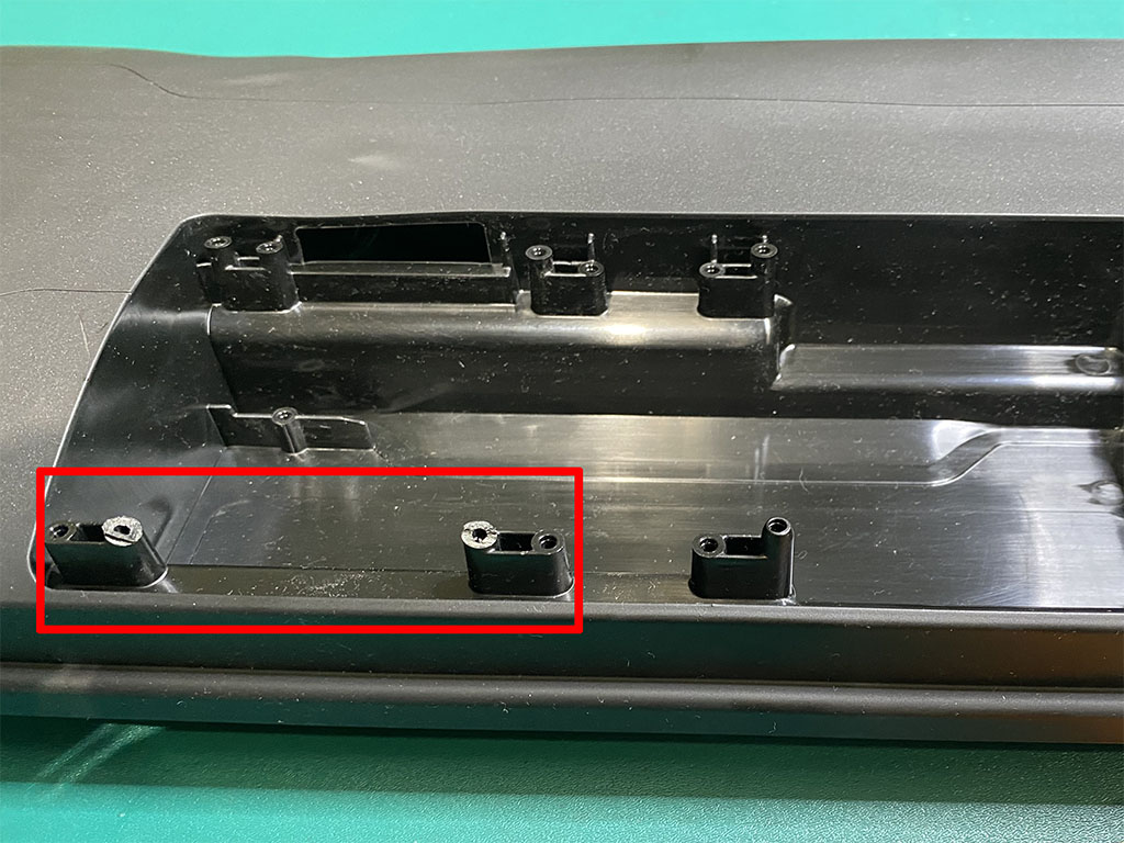
Step 8: IMPORTANT MODIFICATION
If you machine has a serial number earlier than EPRO-15156 you will need to perform this simple modification to allow your new controller board to be seated easily.
Identify the two raised parts of the electronics cavity.
Using a pair of clippers, cut the raised plastic sections as shown in the photos below.
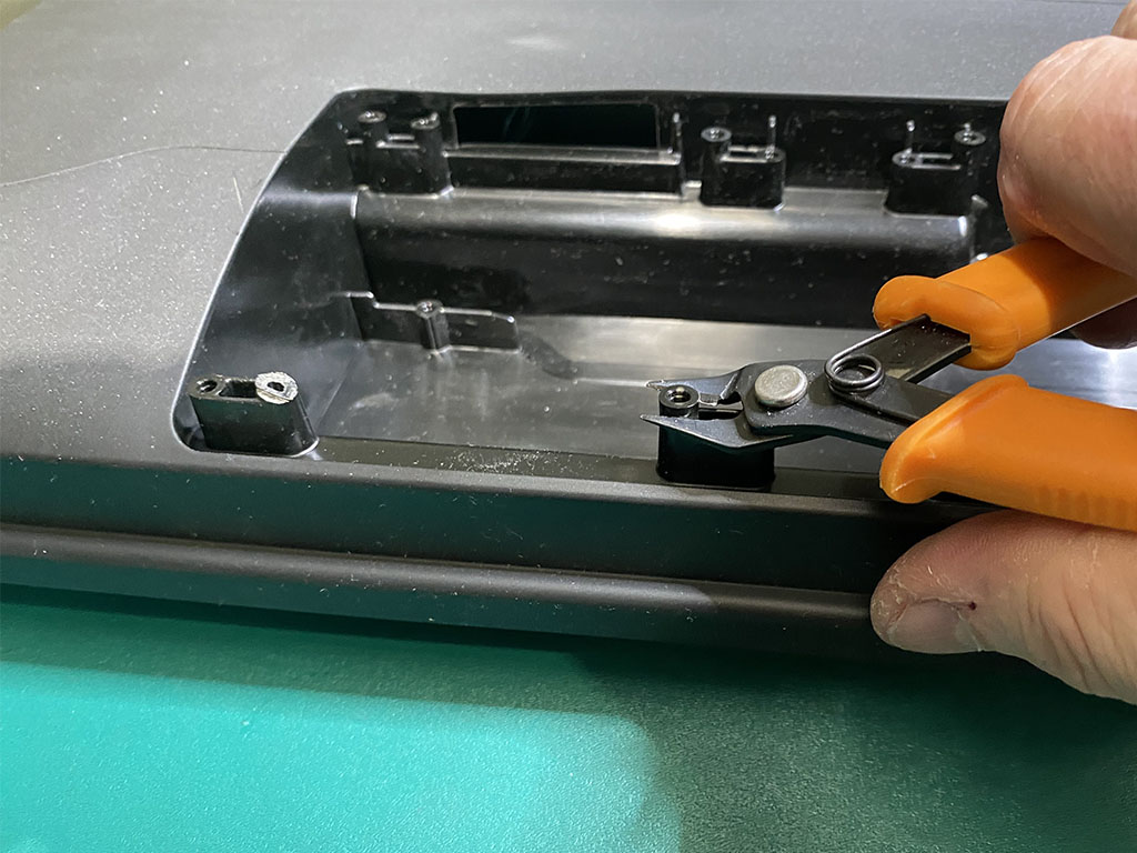
The final result should look like the photo below.
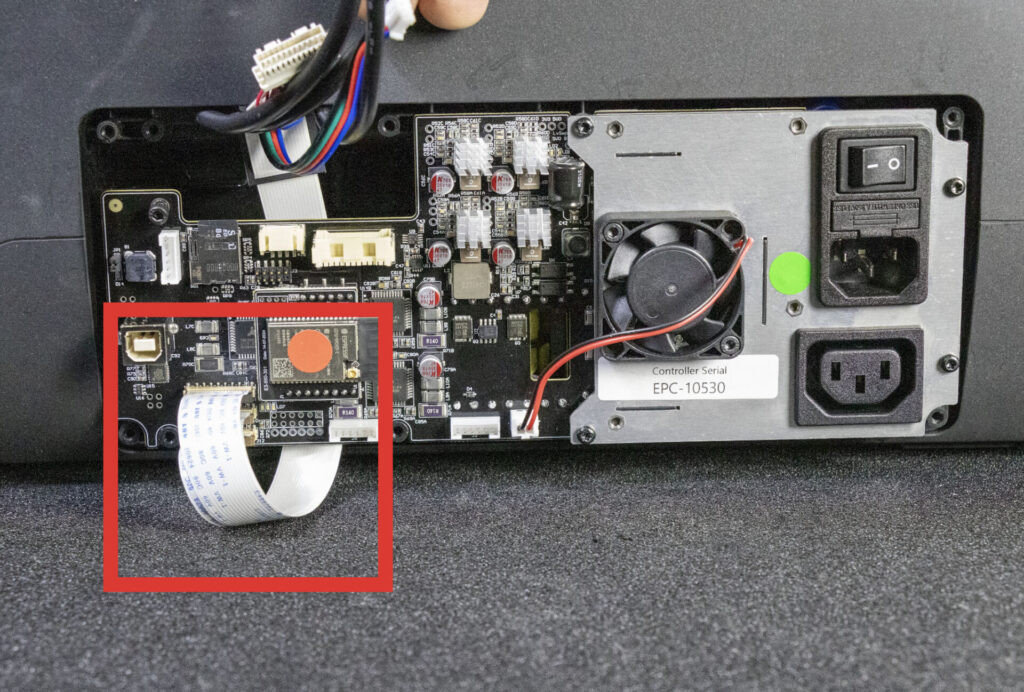
Step 9: Attach the Accessory FFC
Lay your new Controller board down and attach the Accessory FFC.
Step 10: Secure Controller board
Rotate the Controller board into position. Carefully ensure it fits correctly in place before inserting screws.
Ensure the FFC cables are behind the board. all other cables should be in front.
IMPORTANT: Make sure the controller board is sitting flat. NEVER tighten screws if it will cause bending or stress on the board.
When positioned, attach it with the 5 screws previously removed. Remember to place the metal screw into the left-most hole.

Step 11: Connect FFCs
Plug in the 3 FFCs. Make sure they are fully inserted before you lock them in place.
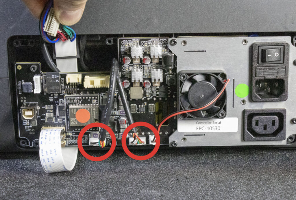
Step 12: Motors
Plug in the 2 motor cables. Note how the excess c able is routed behind the controller PCB.
Step 13: LED and Front Harness
Plug in the LED and Front Harness connectors.
Step 14: Pump Cable
Plug in the pump cable. Note how it is routed.
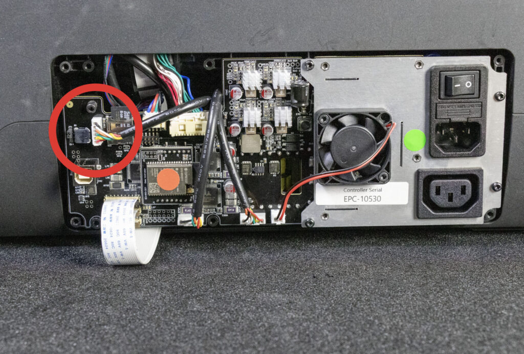
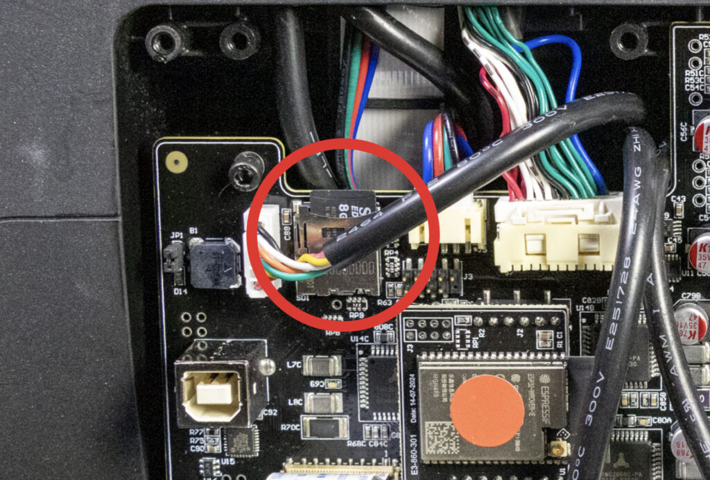
Step 15: SD Card
The SD-Card may be accidentally ejected while handling the board. Make sure it’s correctly inserted.
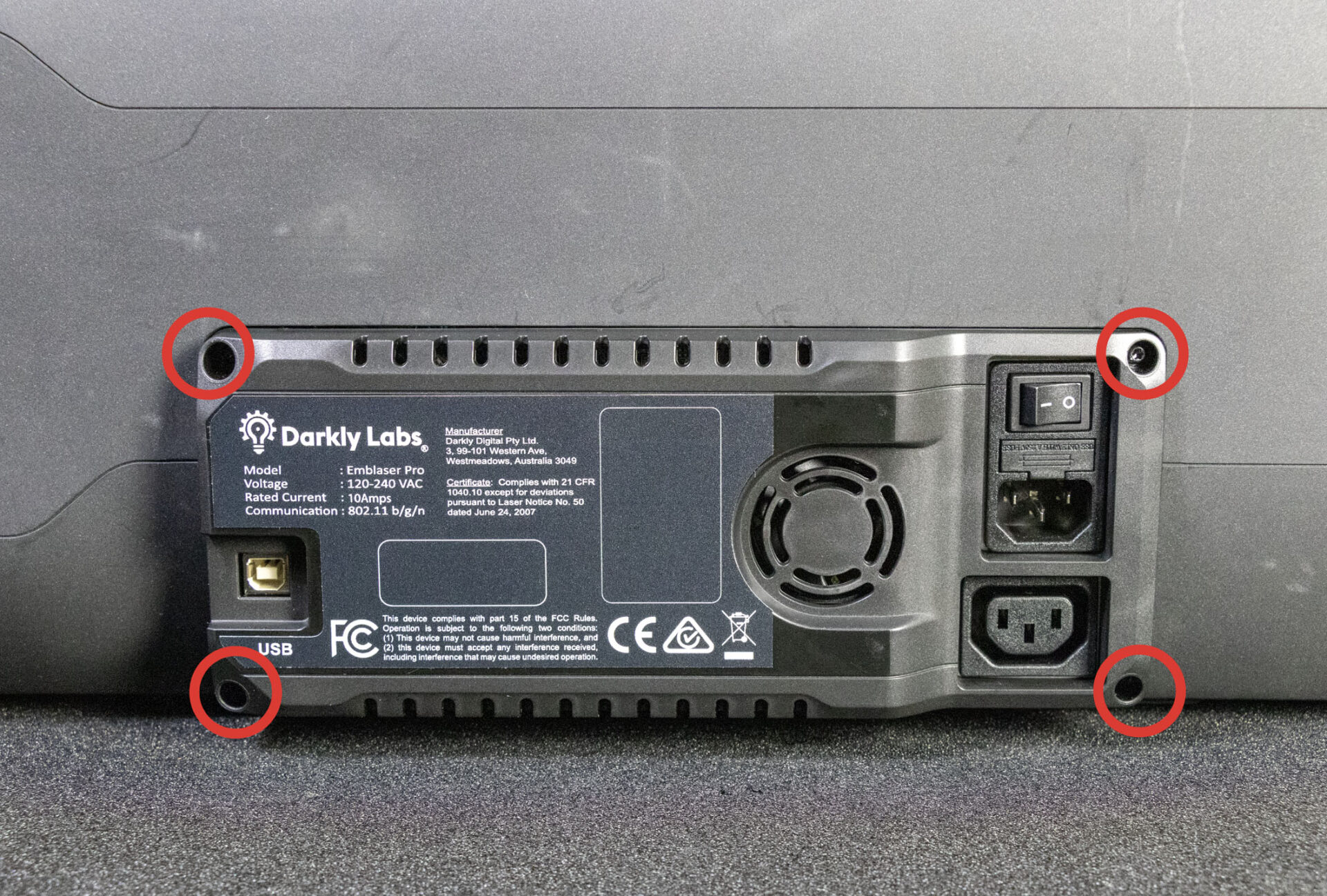
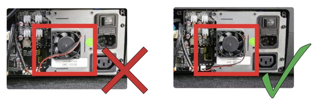
Step 16: Electronics Cover
Before re-attaching the electronics cover, make sure the cooling fan cable is out of the way and does not become trapped against the fan blades.
Re-attach the electronics cover with the 4 plastic screws.