This article will explain how to install the optional V2 Air-Assist accessory on an Emblaser Core.
You will require the following parts:
- Air assist pump
- Air Assist hose
- 3x Air Assist hose clips
- 2x M4x6mm screw
- 2x M4 washer
- 2.5mm Hex Tool (not included)
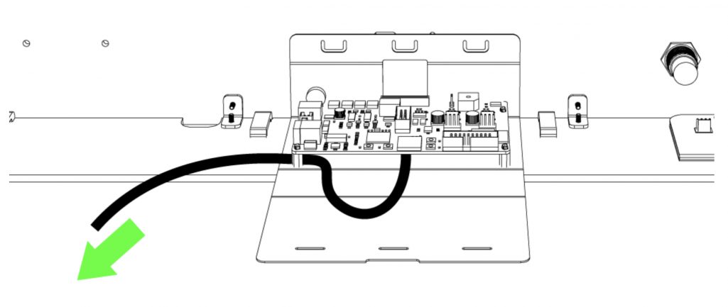
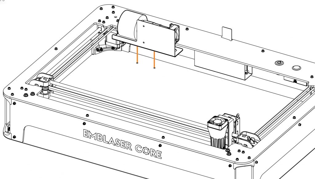
Step 1:
Insert one end of the Air-Assist Hose through the Top Panel as indicated. Pull the end of the Air-Assist Hose past the Controller Board.
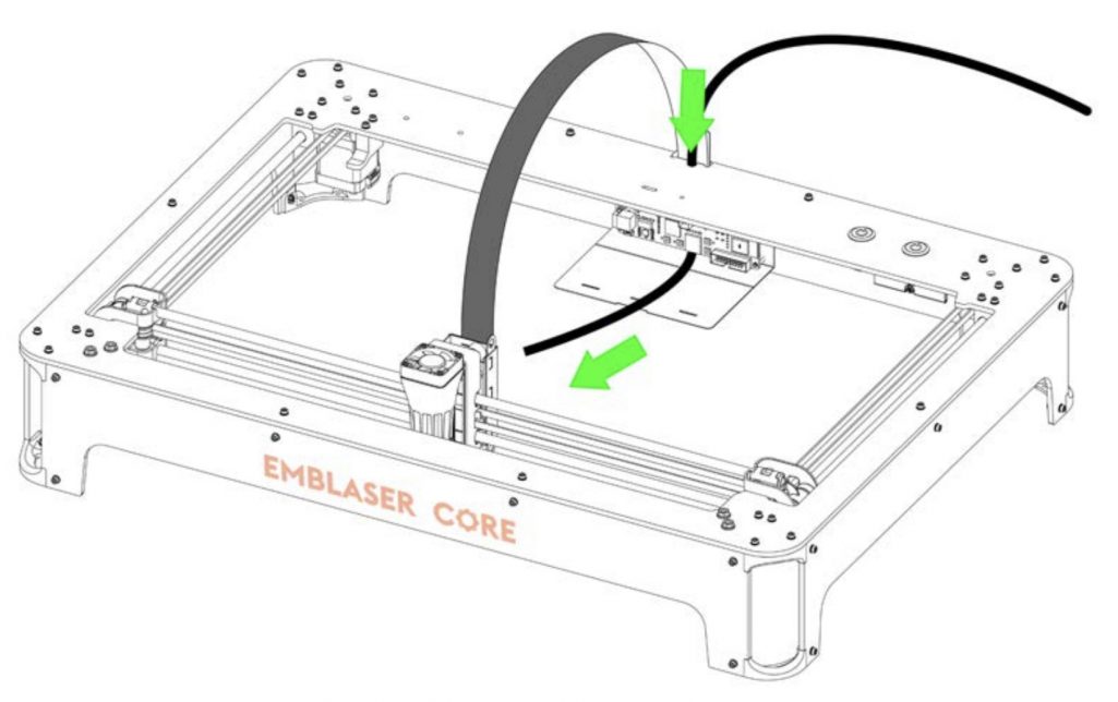
Loop the Air-Assist Hose back under the Controller Board and out the left-hand side.
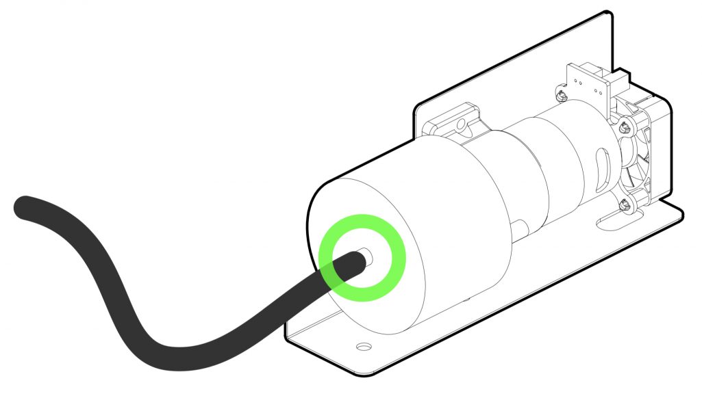
Step 2:
Attach the end of Air-Assist Hose to the OUTPUT of the Air Assist accessory.
Step 3:
Attach the Air-Assist pump to the baseplate using the two M3x6mm screws and washers provided.
Step 4:
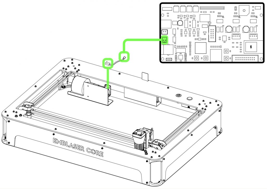
Connect Air-Assist cable to the Controller Board and Air-Assist PCB.
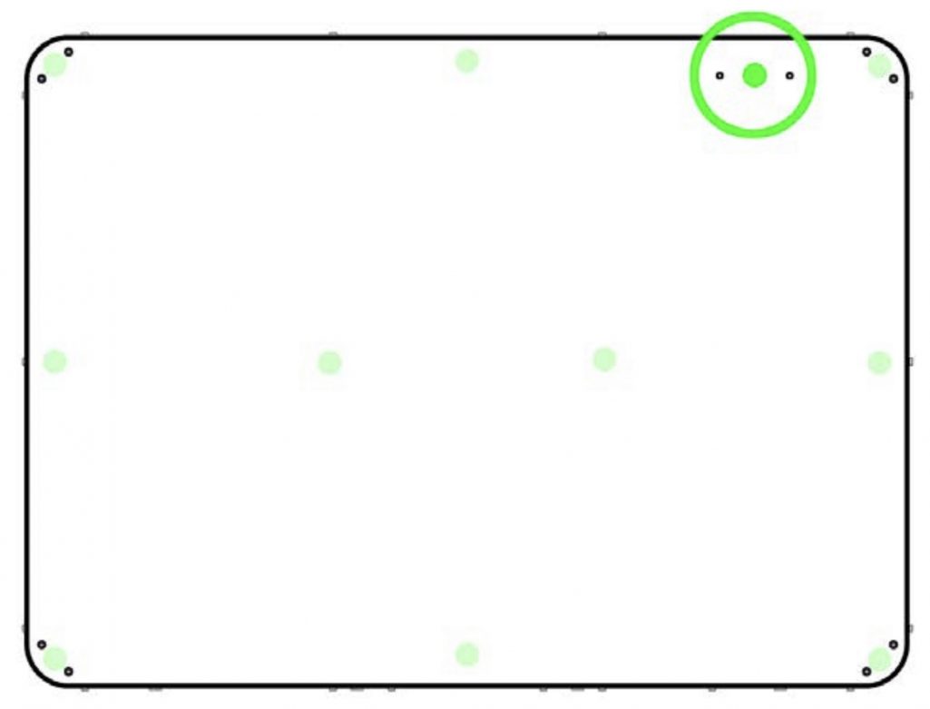
Step 5:
Attach the additional rubber foot supplied with the Air-Assist Accessory to the base plate between the fasteners as indicated.
Step 6:
Route the free end of the Air-Assist Hose through the Driver Board Cover as shown.
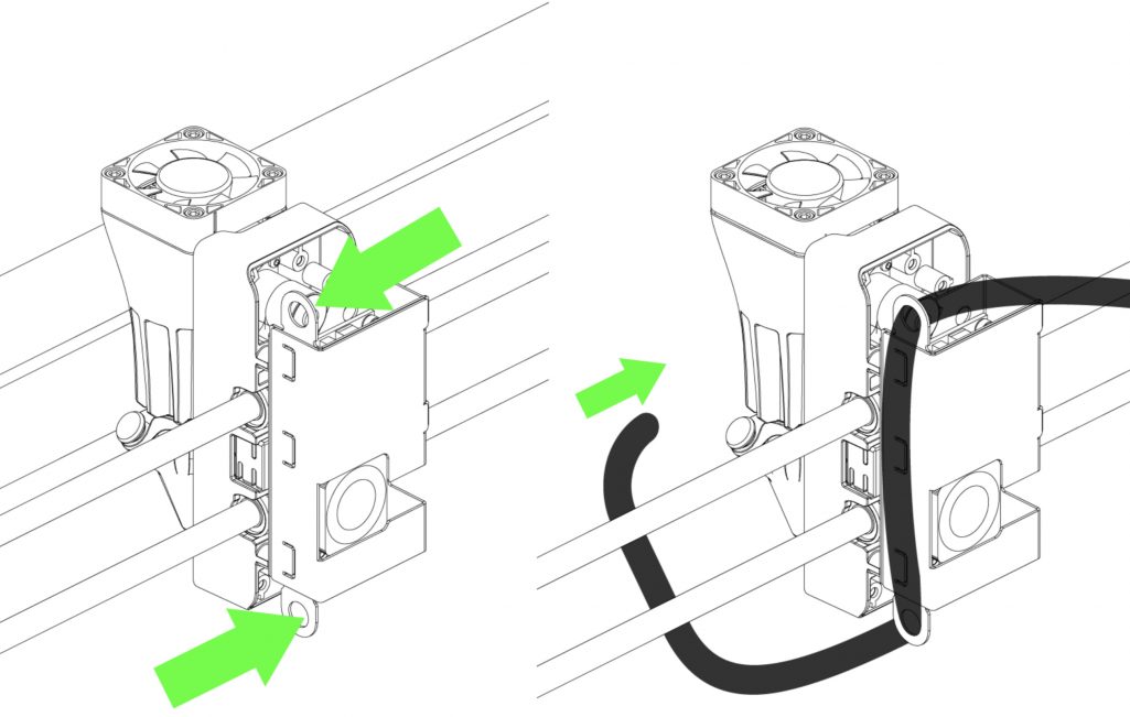
Step 7:
Remove the Aperture Nozzle Plug and insert end of Air-Assist Hose into the Aperture Nozzle.
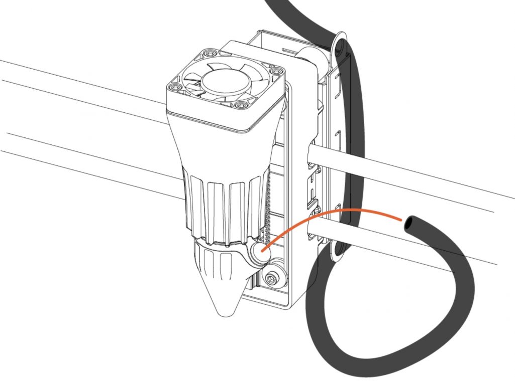
Step 8:
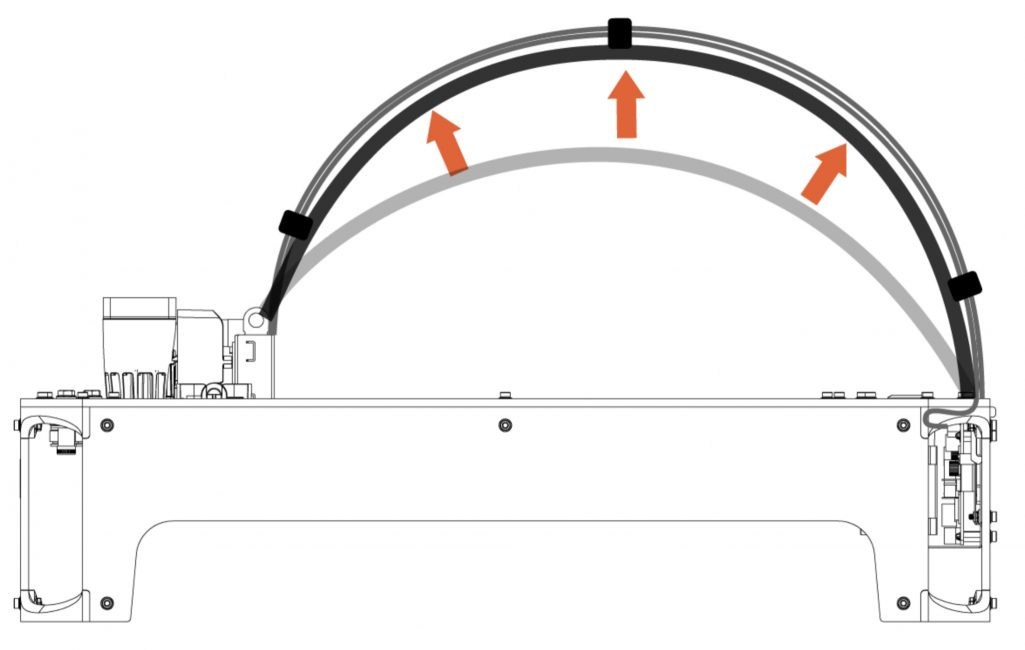
Attach three Air-Assist Hose Clips in the positions shown below. The air-assist hose catch on the clips should face downwards.
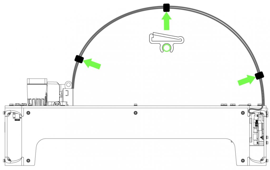
Attach the air-assist hose into its clips.