
This article details the steps required to remove and/or replace the Laser Carriage.
The Laser Carriage Assembly is made up of the Laser Carriage, Laser Driver PCB and Laser Driver Cover. The Laser Carriage runs on three bearings along the X axis of the machine. The Laser Unit is attached to the front of the assembly.
Warning: Do not remove the FFC (Flat Flexible Cable) from the Laser Driver PCB unless also replacing the Laser Driver PCB, or otherwise directed to do so. The connector is extremely delicate and should not be removed unless absolutely necessary.
Step 1:
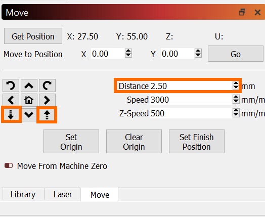
Turn on your Emblaser 2 and use the Move tab within LightBurn to lower the Laser Unit to its lowest position.
Turn off your Emblaser 2 and unplug the power cable.
Step 2:
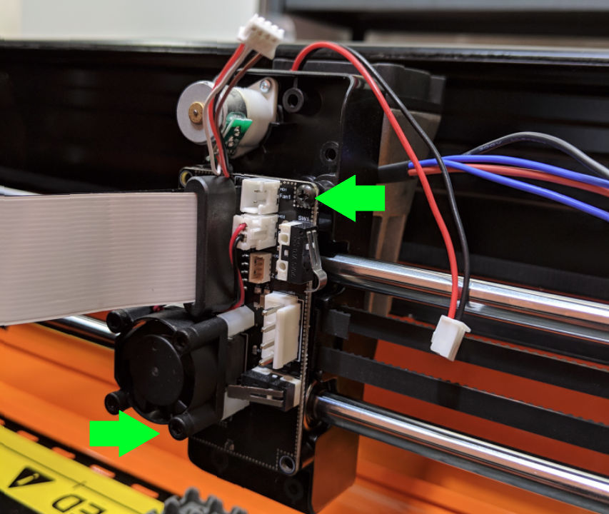
Use a Philips head screw driver to remove the two indicated screws.
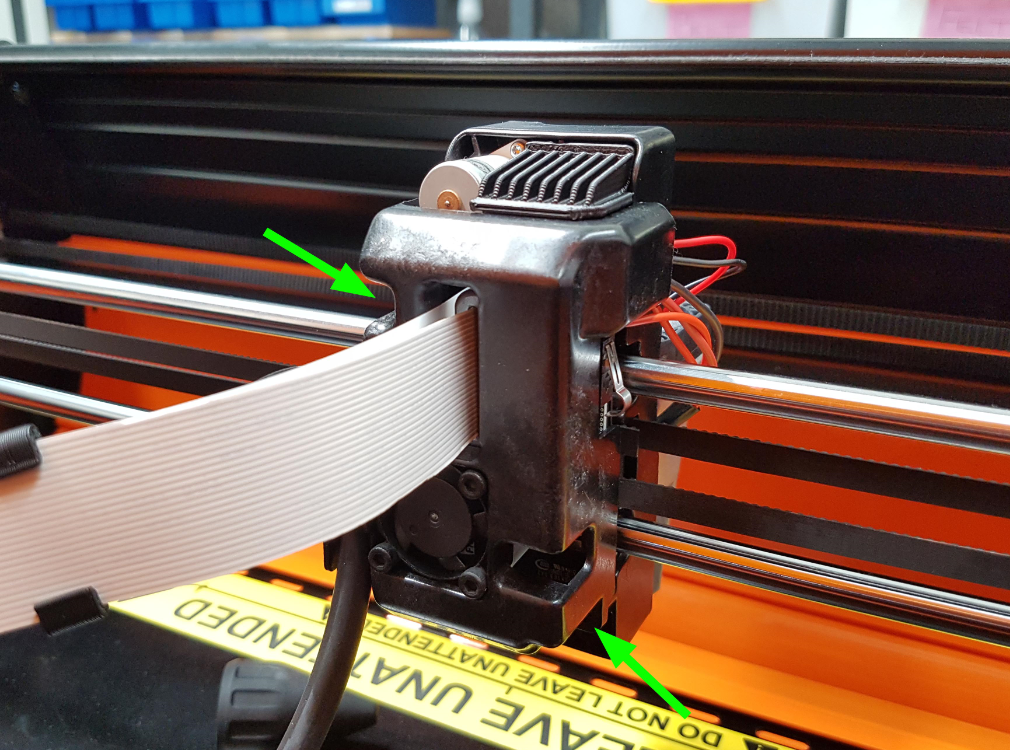
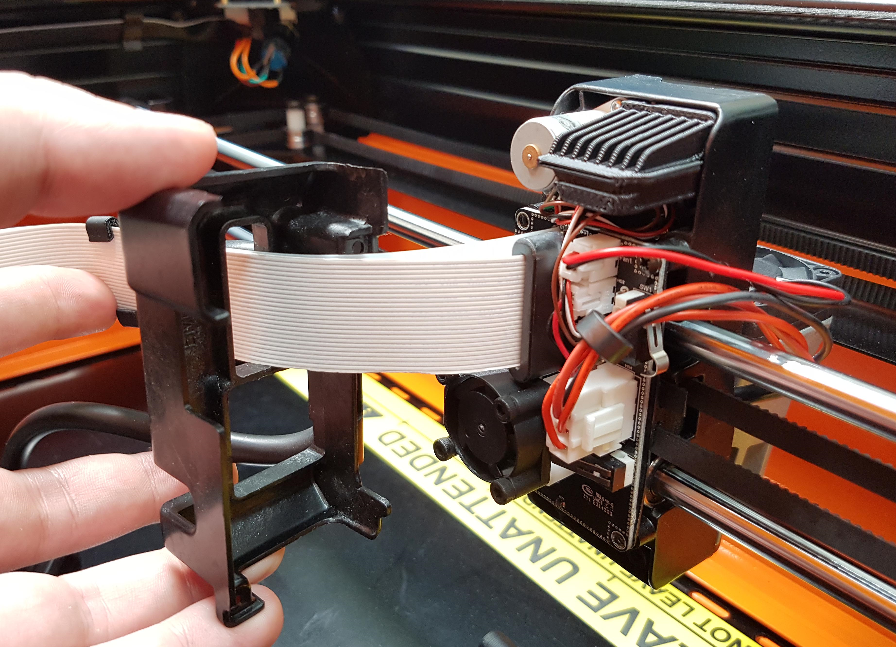
Remove the Laser Carriage Cover.
(Take note of where the cables and interior components sit, these will need to be returned to their positions when the Laser Carriage Cover is reattached.)
Step 3:
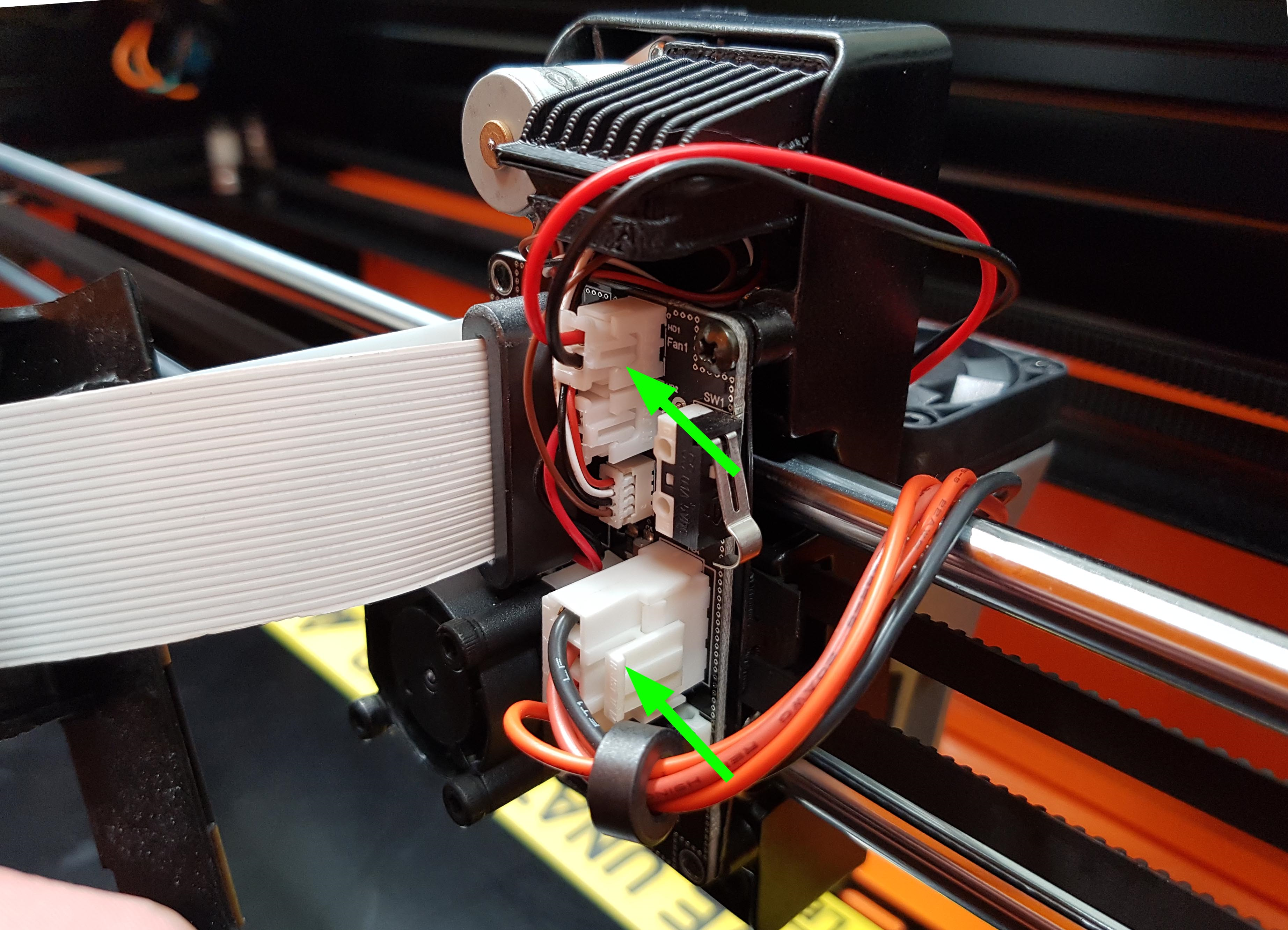
Unplug the Laser Diode and the Laser Heatsink Fan connectors from the Laser Driver PCB.
Step 4:
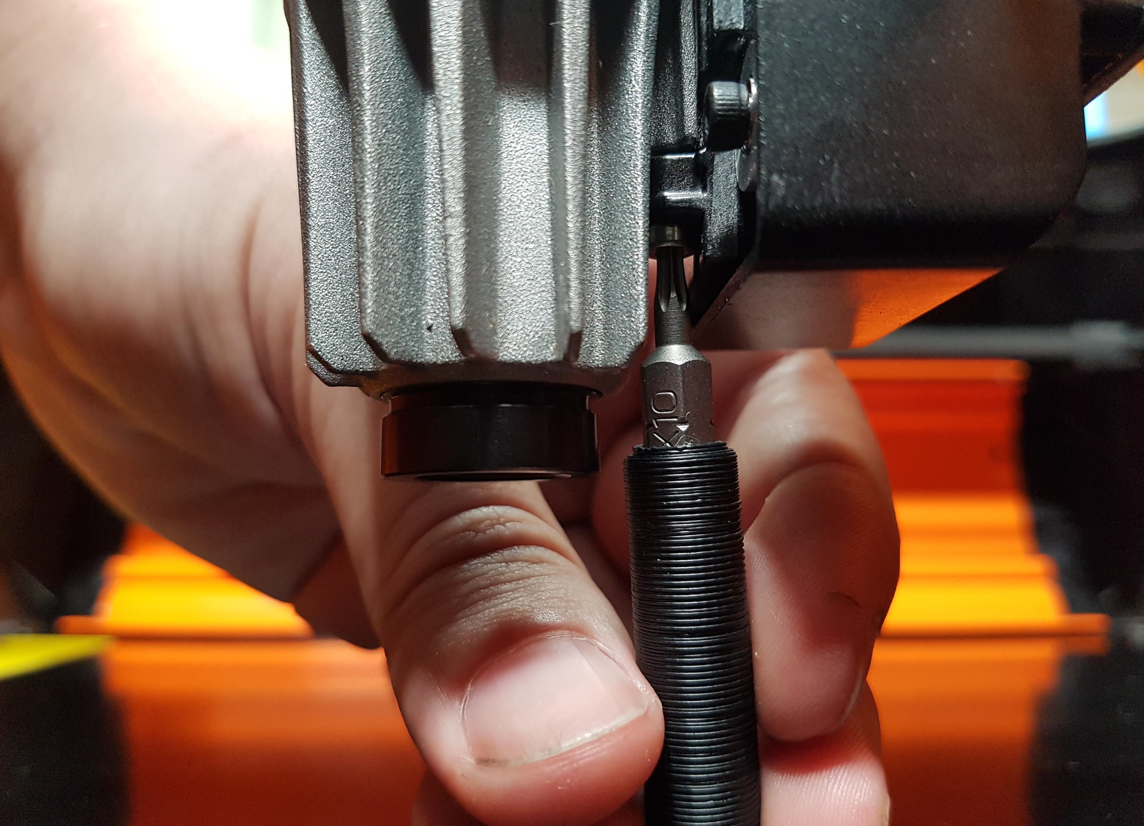
With the Laser Unit moved to the lowest position, use either a TORX T10 bit, or 2mm Hex key (supplied with your Emblaser tool kit) to unscrew the fastener retaining the Laser Unit to the Laser Carriage.
Step 5:
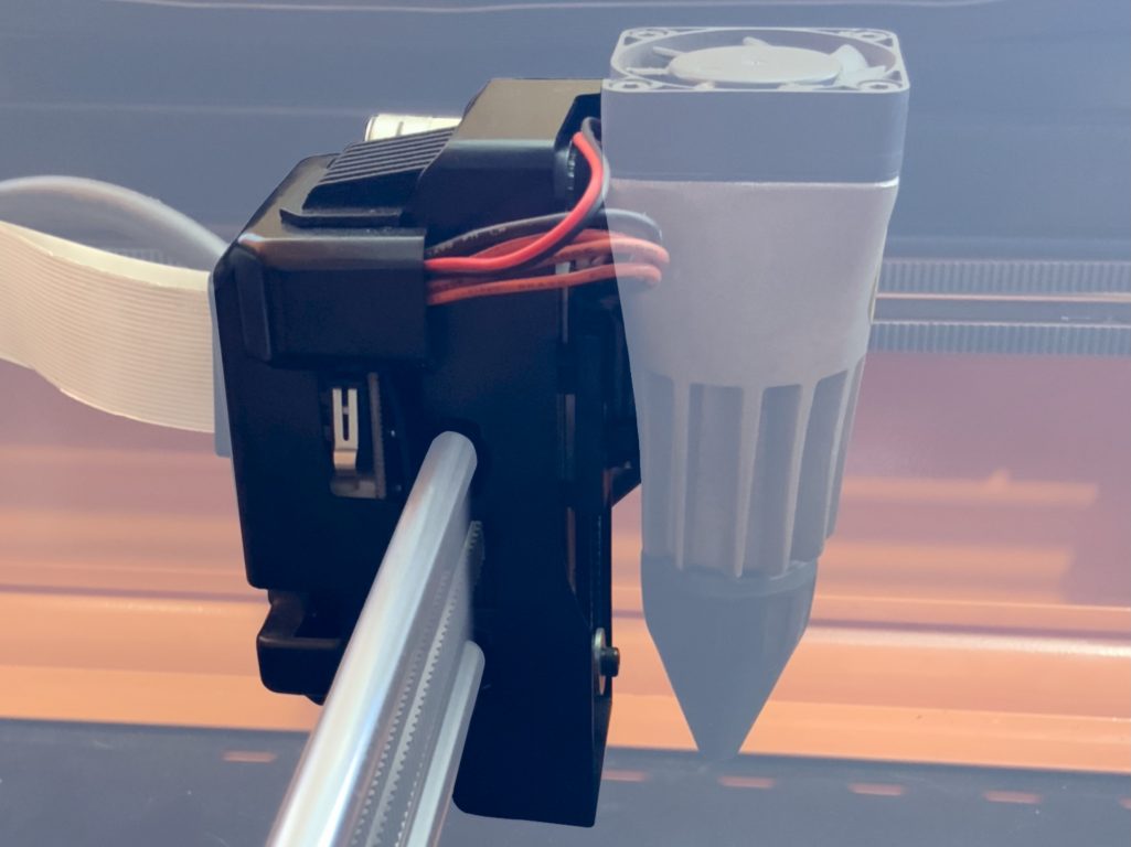
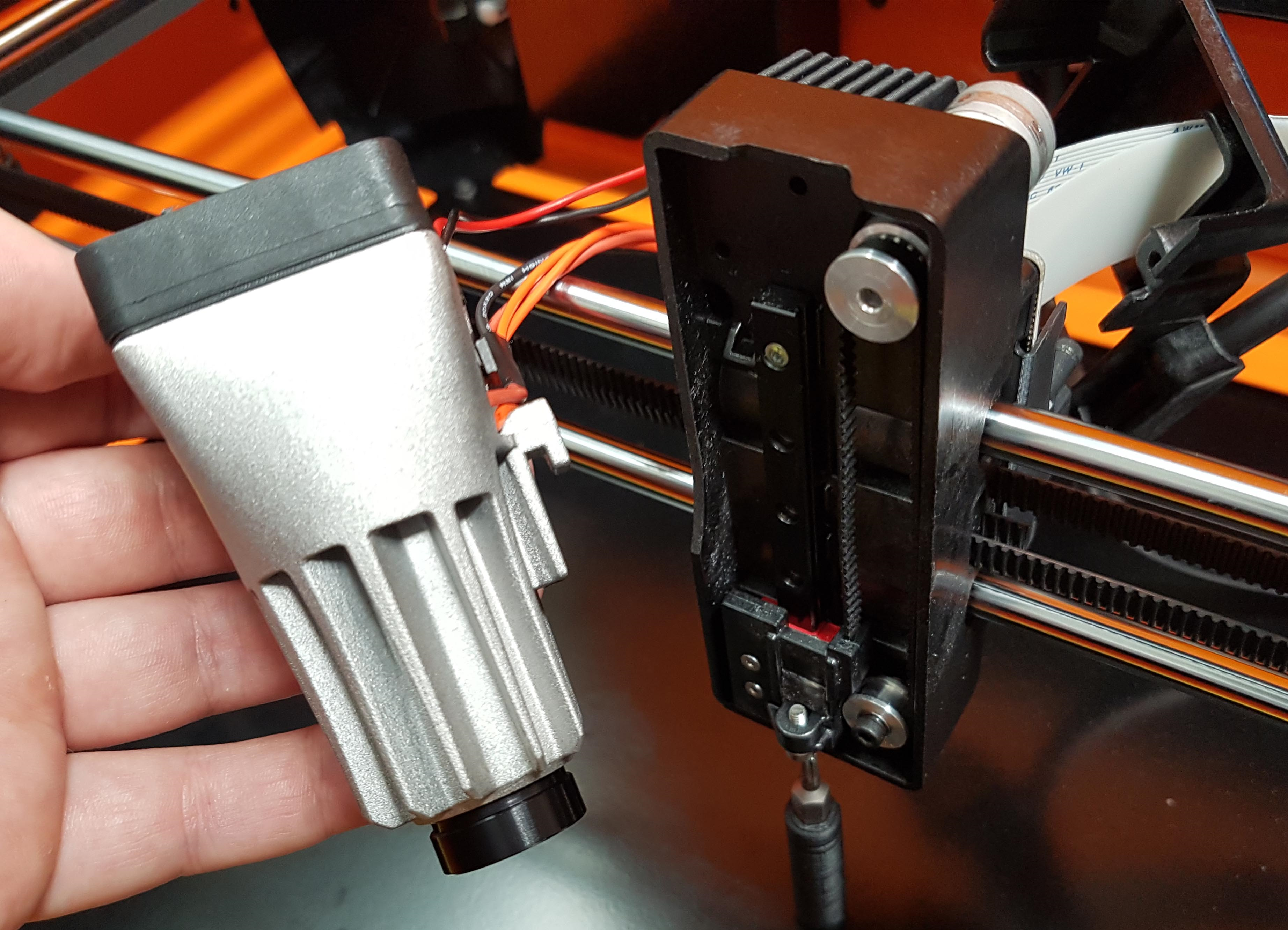
Remove the Laser Unit, taking care to keep the exposed Focus Lens free of finger prints.
Replace the Nozzle to keep the Focus Lens protected
Step 6:
Remove the screws retaining the Laser Driver PCB to the Laser Carriage, then carefully place to one side.
Step 7:
The Belt Hub is located between the two rails at at the rear of the Laser Carriage. With the Laser Driver PCB removed, the Belt Hub can be freed from its position on the Laser Carriage.
Step 8:
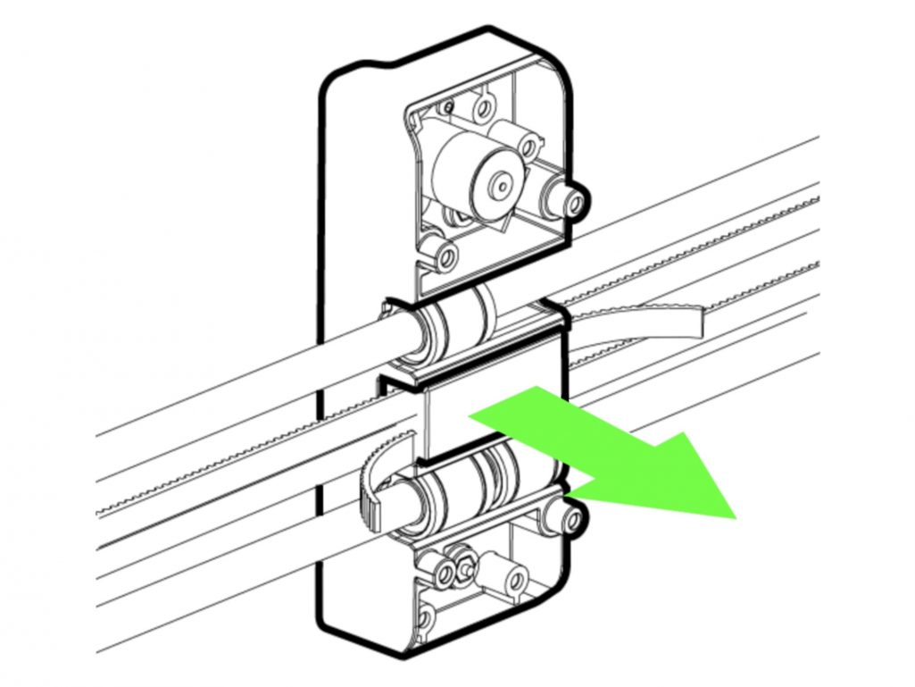
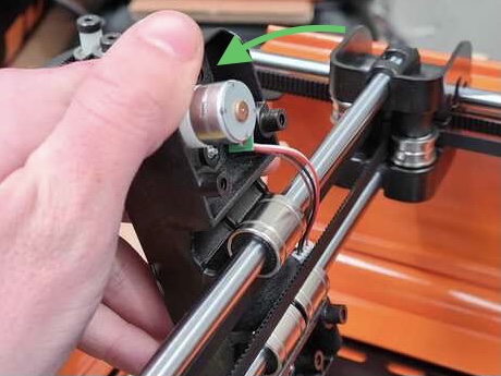
With only the Laser Carriage remaining, carefully twist the top towards the front of the Emblaser to free the top Linear Bearing.
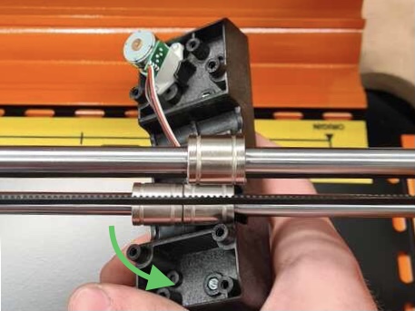
Step 9:
Next, carefully twist to the side to free the Laser Carriage from the lower two Linear Bearings.
Step 10:
To reattach the Laser Carriage and reassemble, or to attach a new Laser Carriage simply perform these steps in reverse.
If you have any difficulty with the above process, please contact support@darklylabs.com and note the step you are having difficulty with.
