
There are Gantry Carriages on the left and right side of the device. This guide explains the steps to replacing a gantry carriage in the rare event one becomes damaged. This guide focuses on one Gantry Carriage however it is applicable to both left and right.
Step 1:
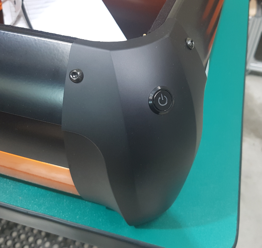
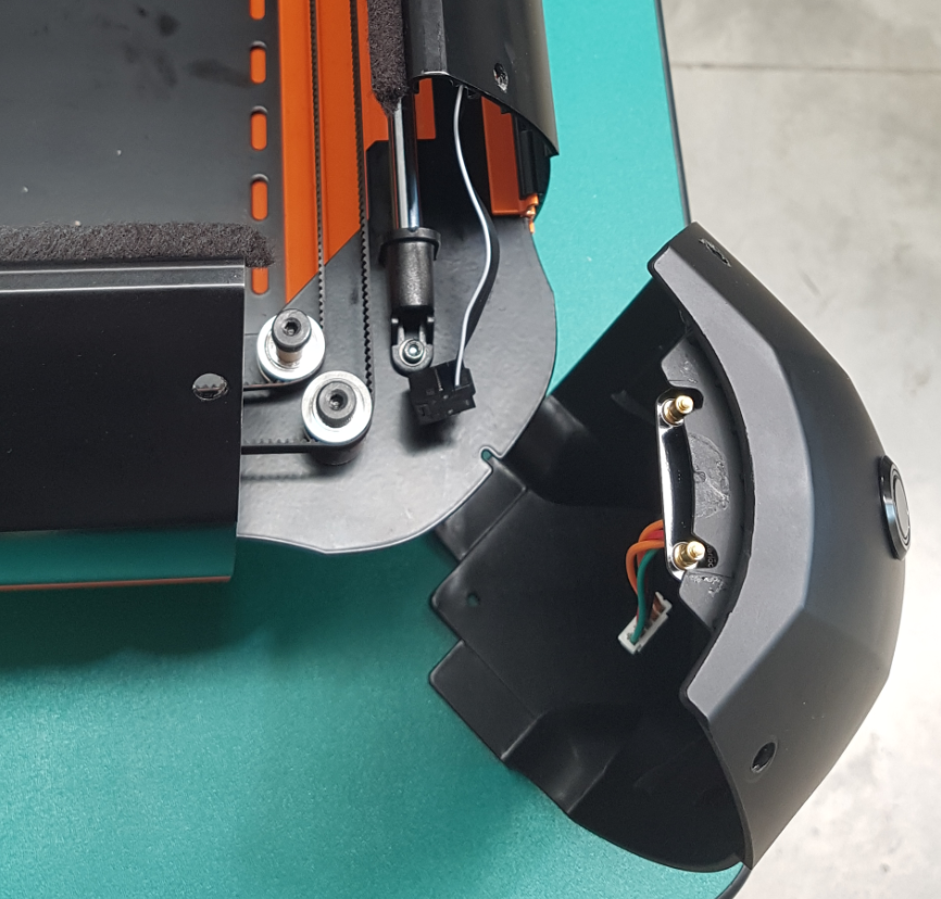
For ease of access, the front corner closest to the damaged Gantry Carriage should be removed.
Disconnect all the cables from the PCB.
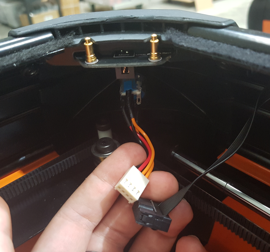
Carefully peel the ends of the felt strips away from the corner.
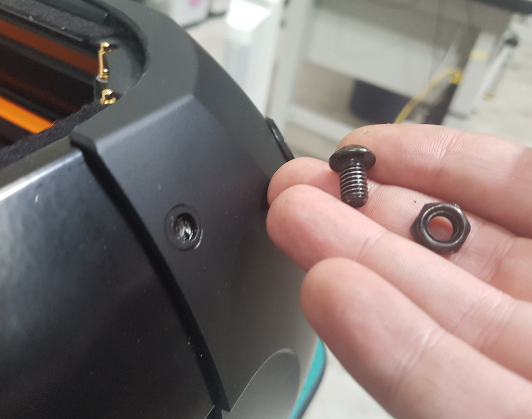
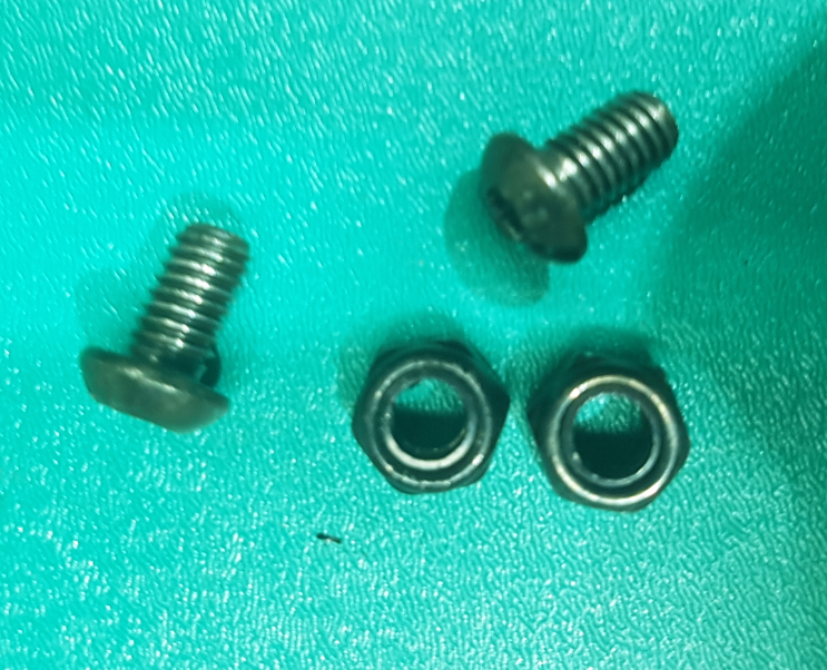
Step 2:
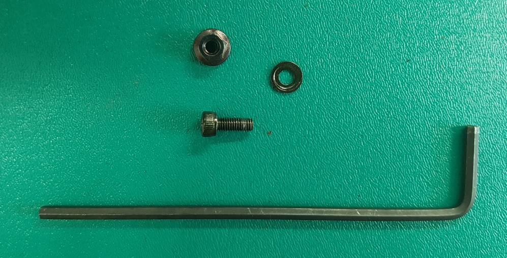
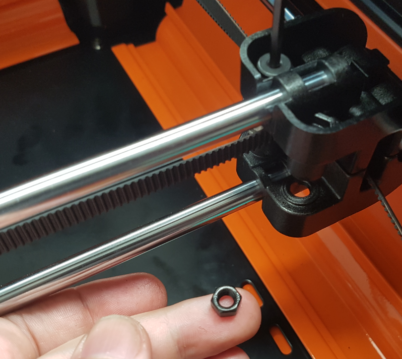
Using a 4mm Hex Tool, remove the two large bolts and nuts from the top of the corner.
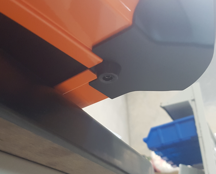
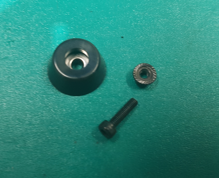
Step 3:
Using a 2.5mm Hex Tool, remove the bolt and nut holding the rubber foot underneath the corner.
Carefully pull the corner away from the housing.
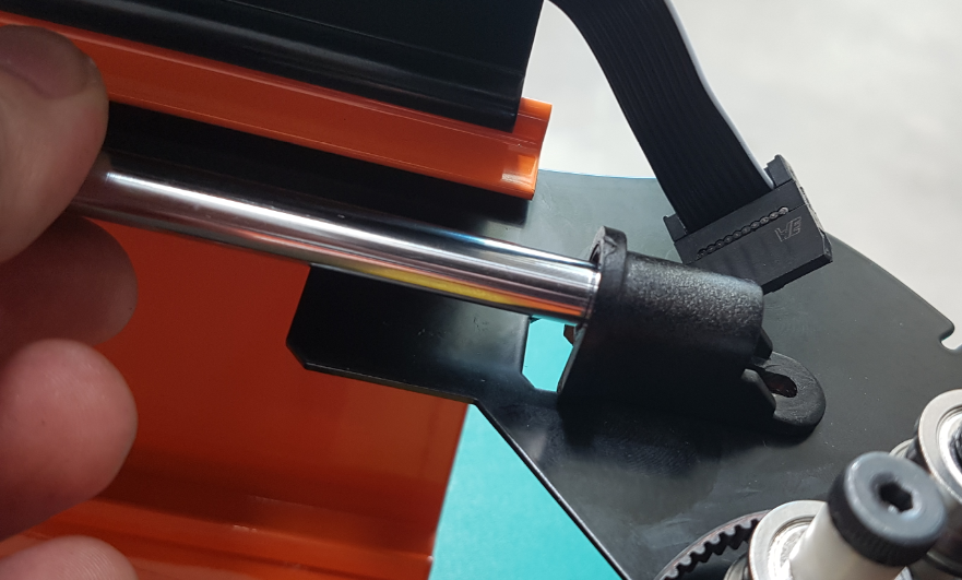
Step 4:
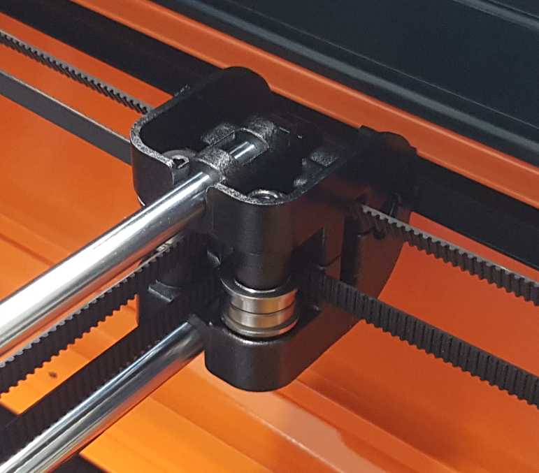
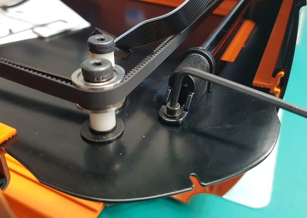
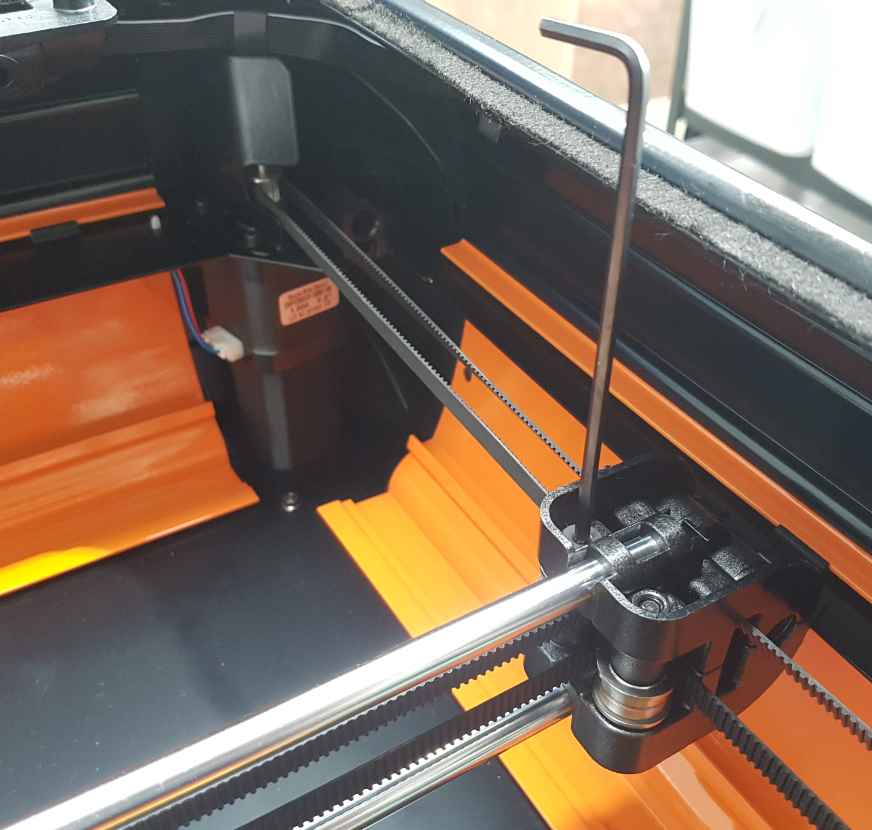
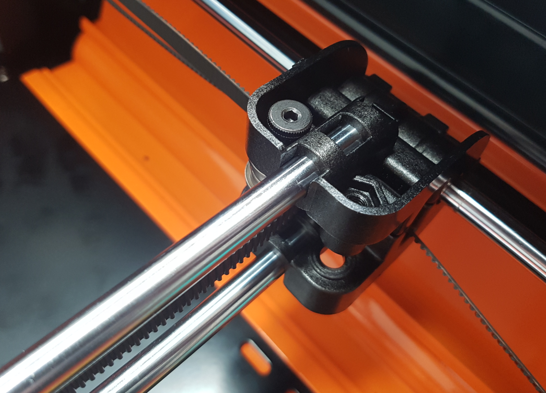
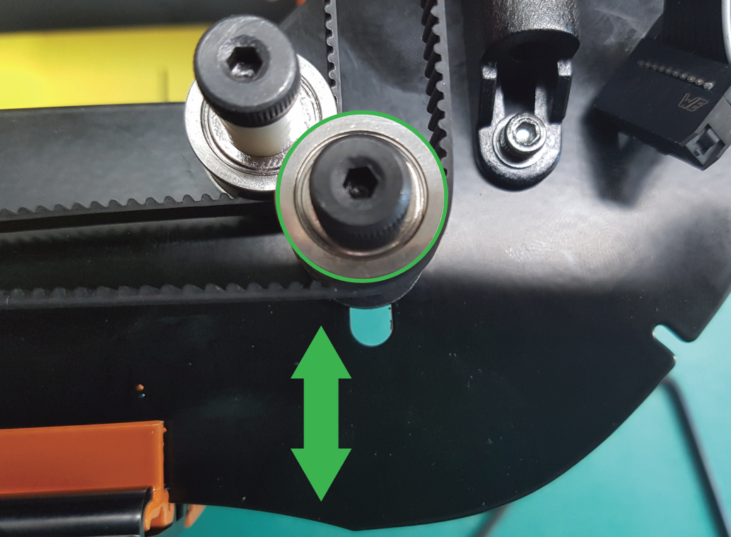
Loosen the shoulder bolt closest to the front of the machine. This will allow it to shift back and relax the tension on the belts.
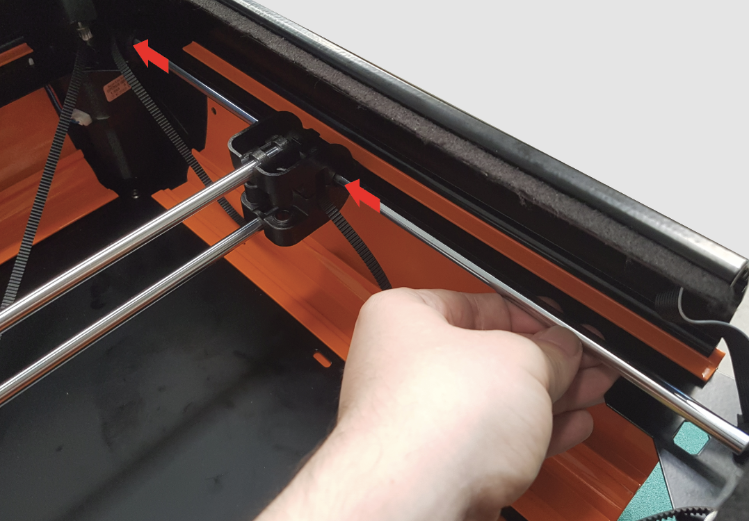
With the corner out of the way, the Rail Mount can be removed using a 2.5mm Hex Tool.
Carefully remove the rail from the opposite Rail Mount. Pull it gently through the Gantry Carriage.
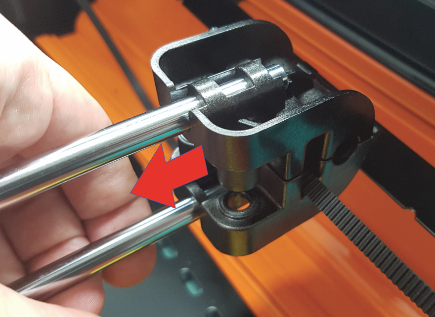
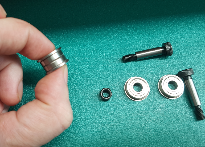
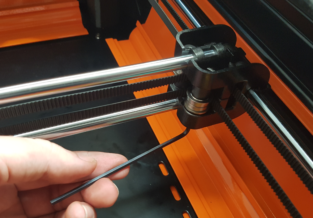
Step 5:
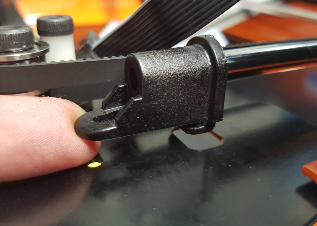
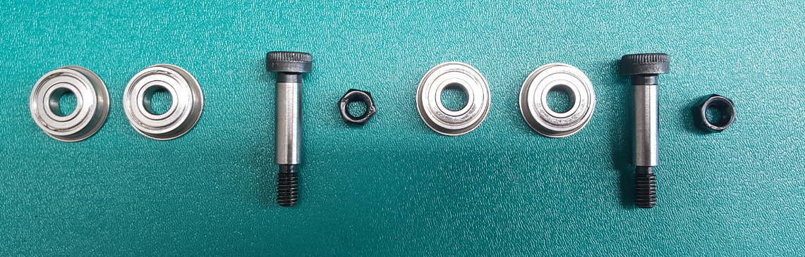
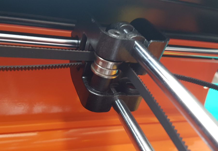
Remove the Shoulder Bolts from the Gantry Carriage. This will release the Flanged Bearings and free the belts.
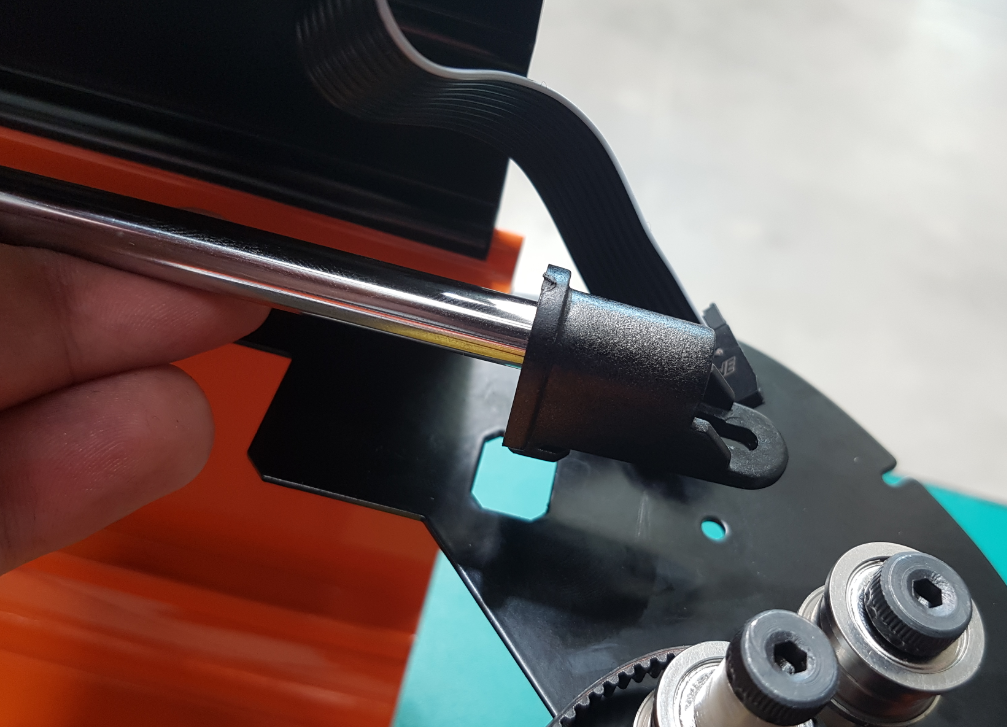
Step 6:
Gently slide off the front end of the side extrusion, this will give you better access to the Gantry Carriage.
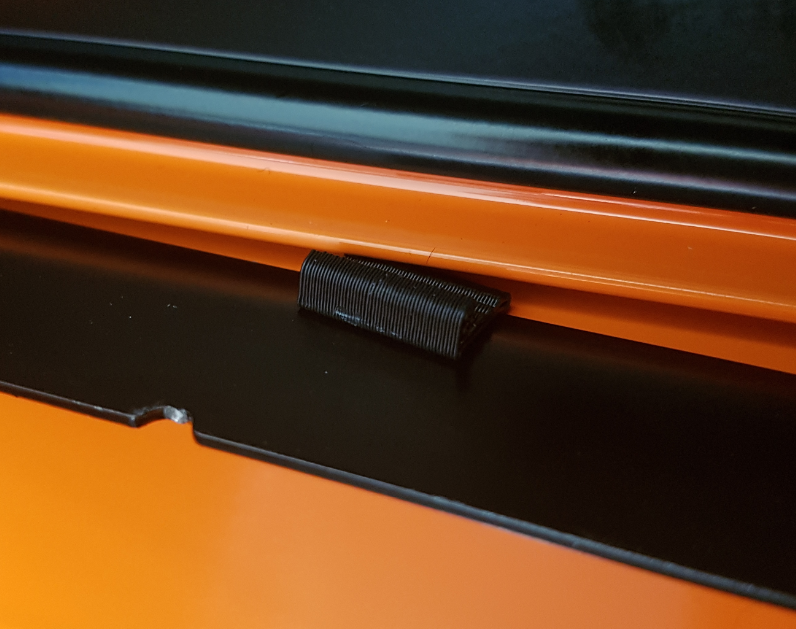
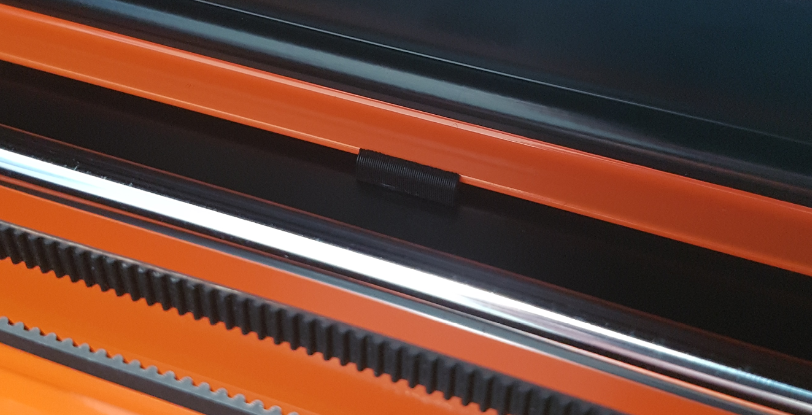
Sliding the Extrusion free may dislodge a small plastic wedge. If this wedge falls out (it is not in every machine) put it in a safe place, its reassembly comes last.
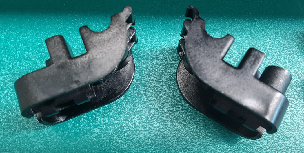
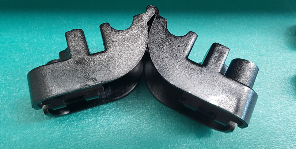
Slide the Gantry Carriage from the rails, this may be on tight and could take some wiggling.

Step 7:
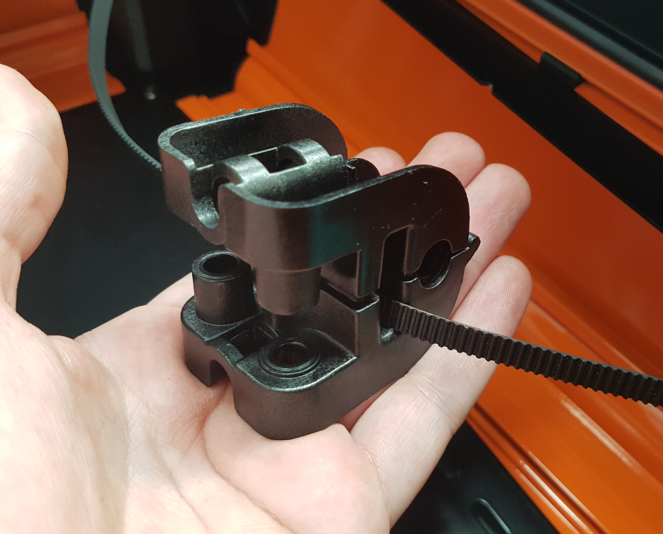
Assembling your replacement Gantry Carriage.
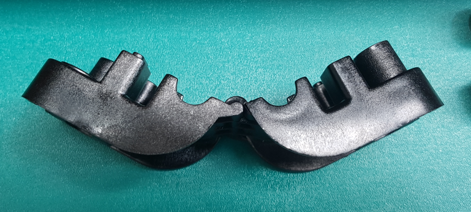
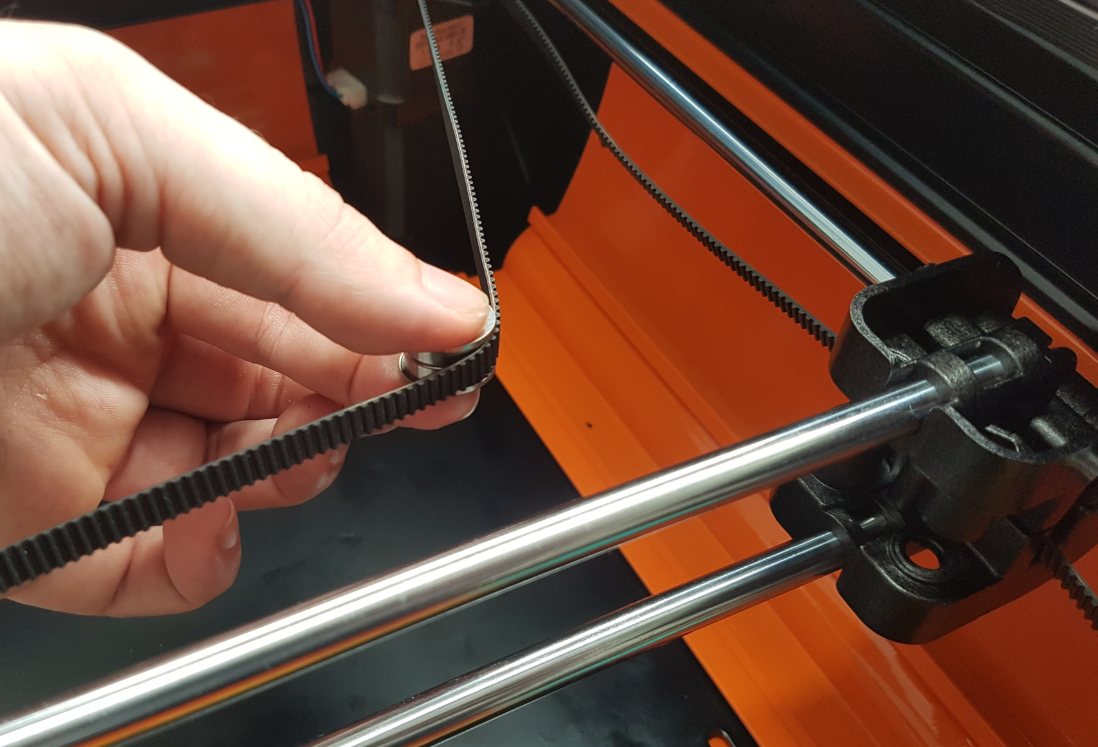
Step 8:
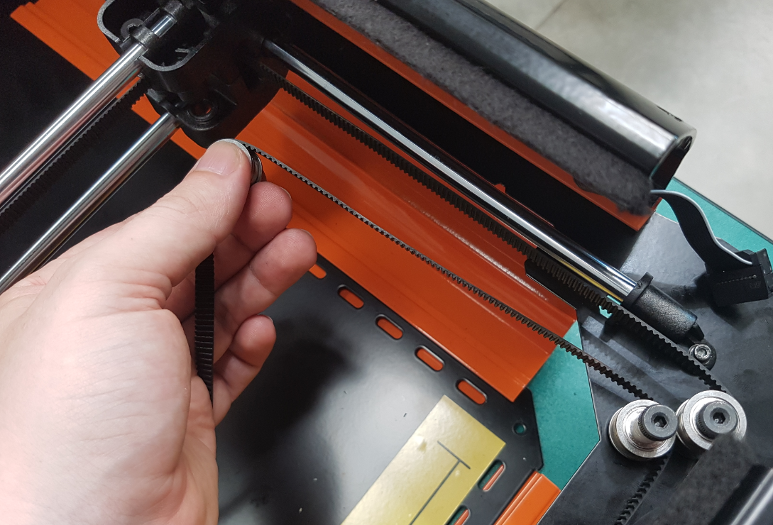
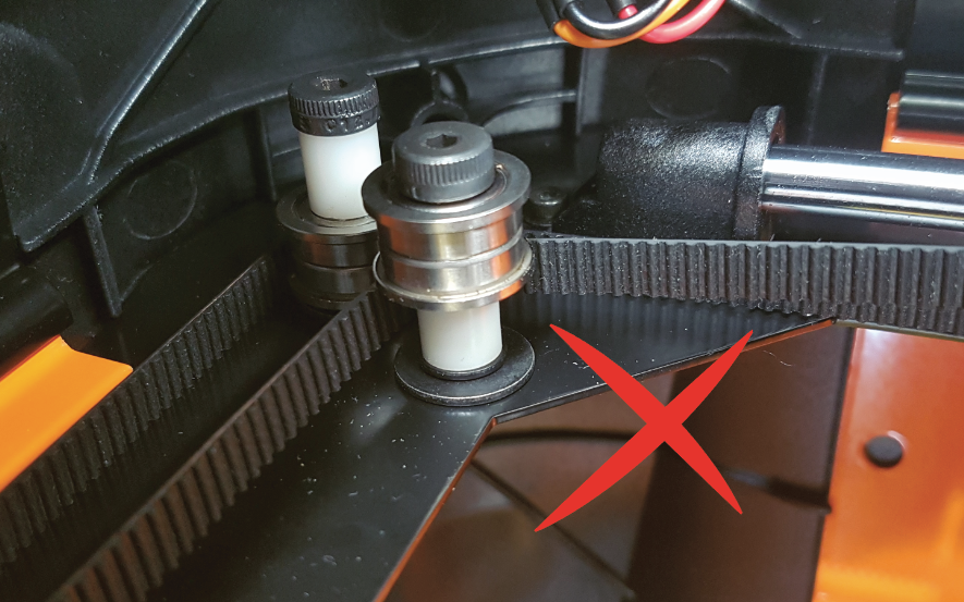
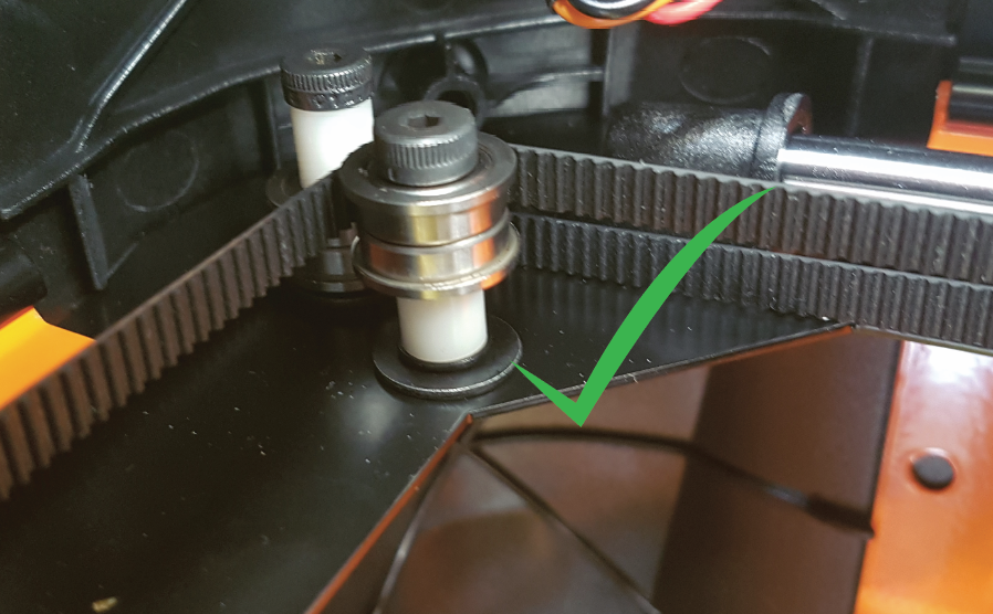
Reassembly requires careful attention to belt positions.
Take the portion of Belt highlighted in green and place it into the Gantry Carriage as shown.
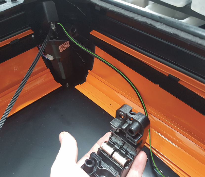
Reattach the Gantry Carriage to the Rails.
Reattach Rail Mount.
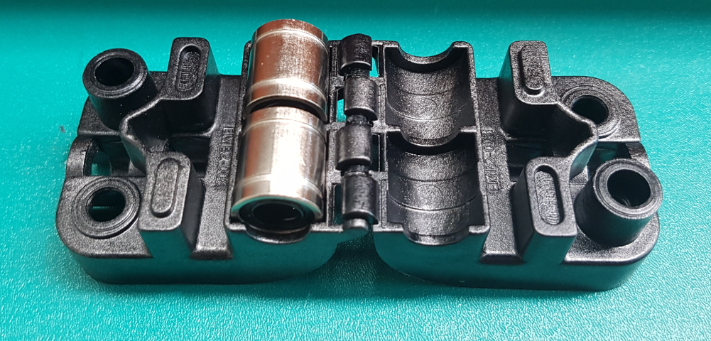
Step 9:
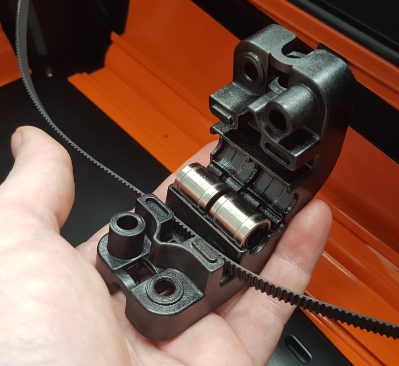
Reassembling the Gantry Carriage requires that the belts be in place when the bearings are attached.
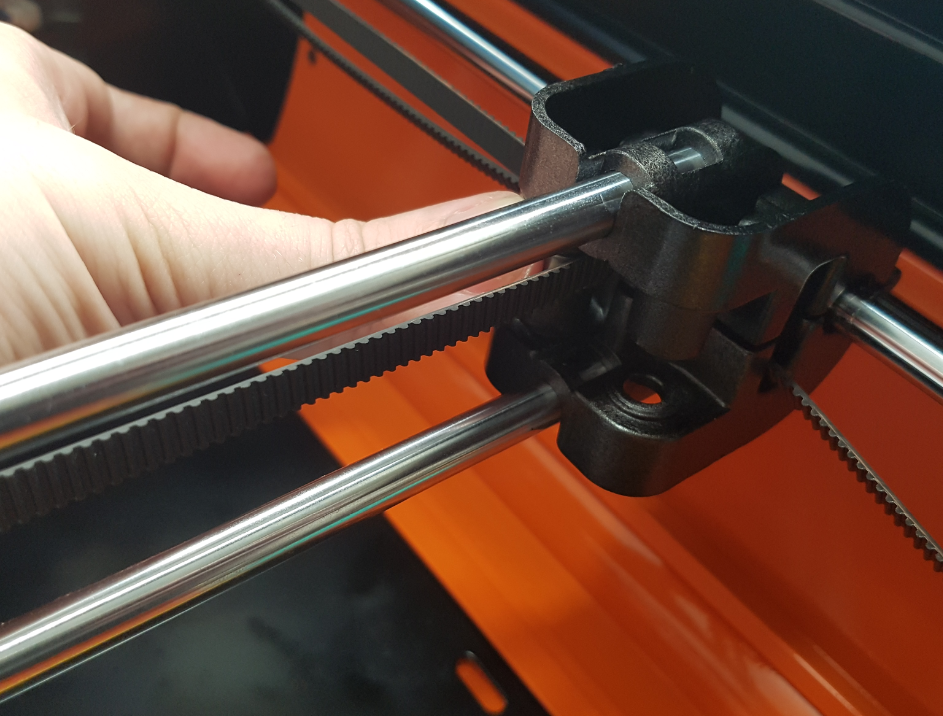
Repeat for second belt.
Step 10:
Visually inspect belts for twists and improper routing.
When the belts are loosened they can potentially slip free of their bearings.
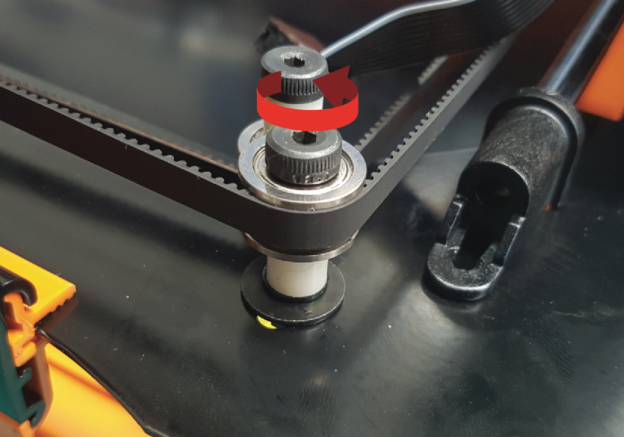
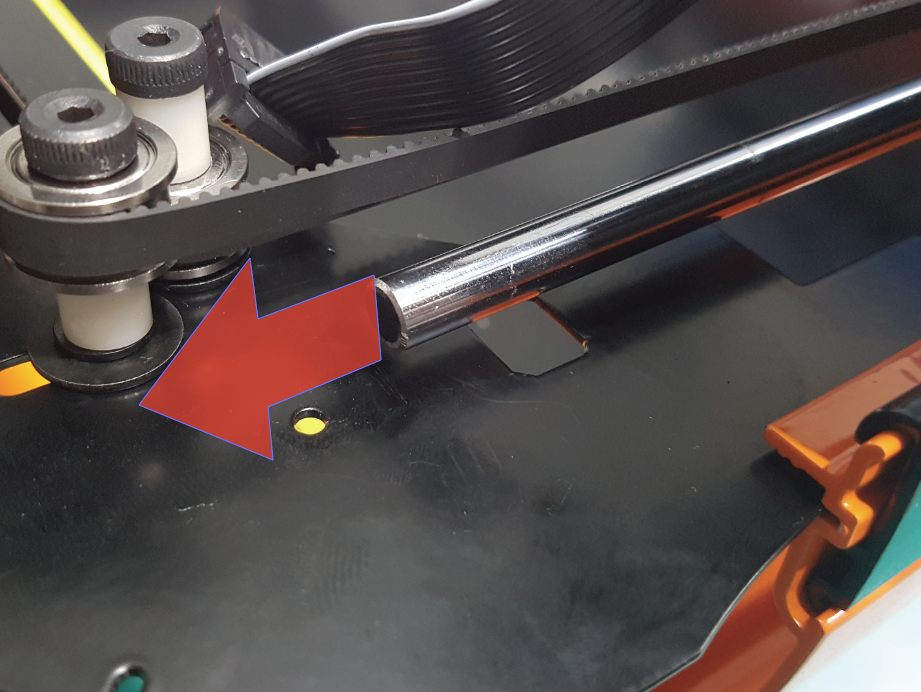
The when the Gantry Carriages are pulled to the front, they must meet the end of their path at the same time.
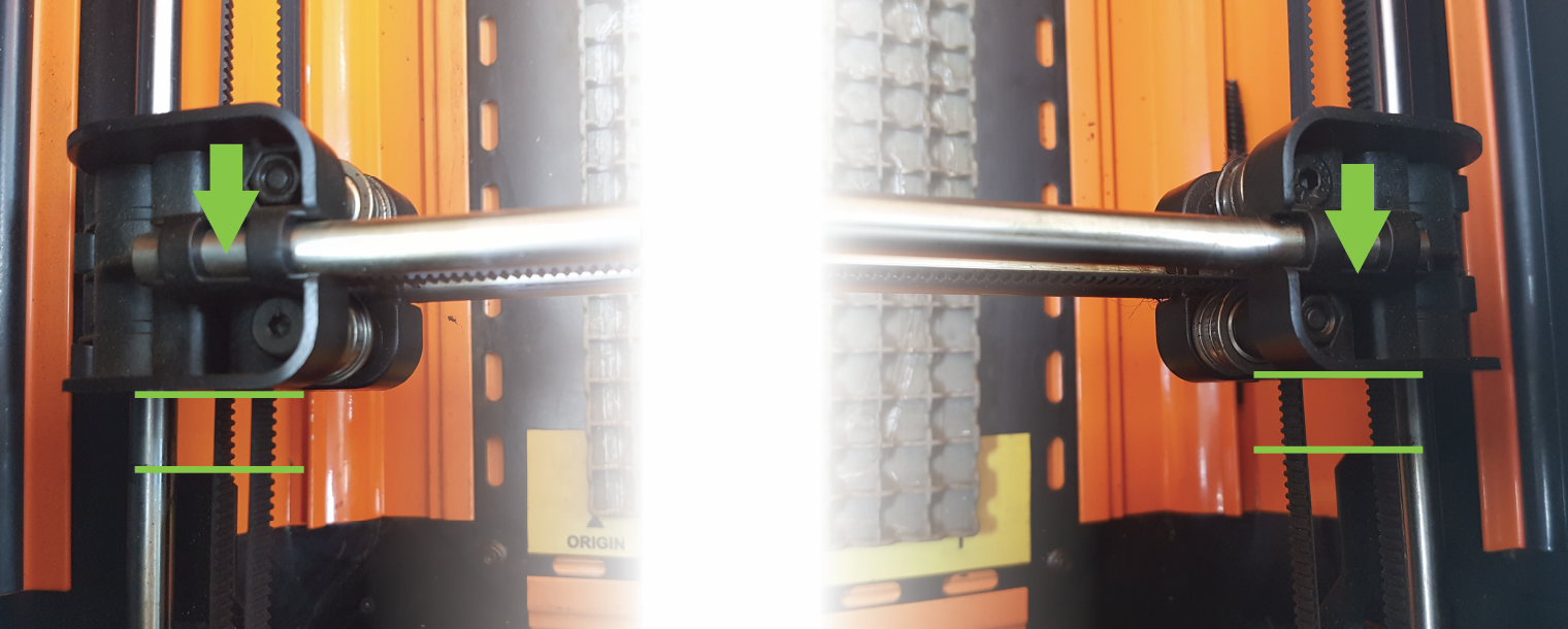
This is achieved by adjusting the belt tension. To adjust belt tension, move the indicated bearing backwards or forwards in its slot until the desired belt tension is achieved. Fasten tightly to lock this tension in.
Step 11:
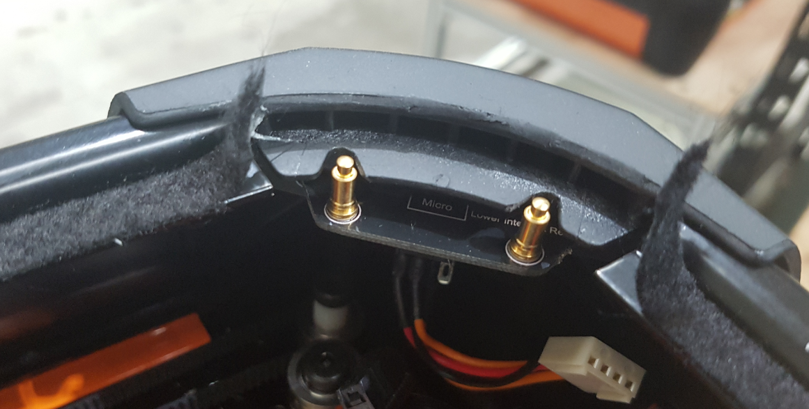
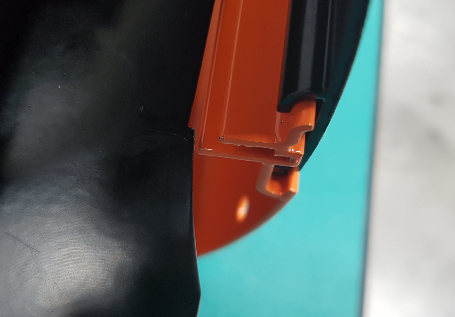
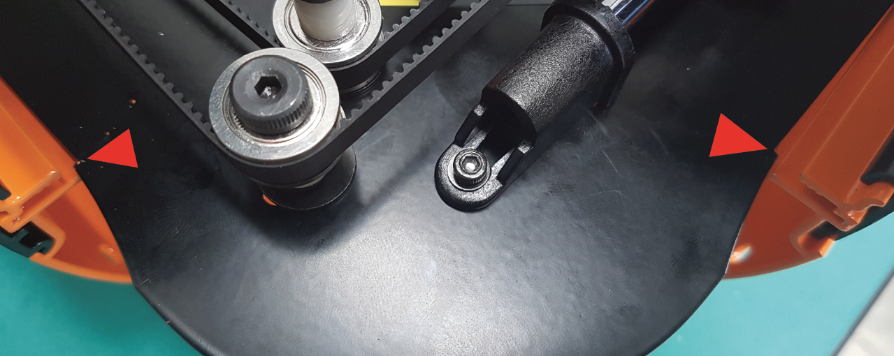
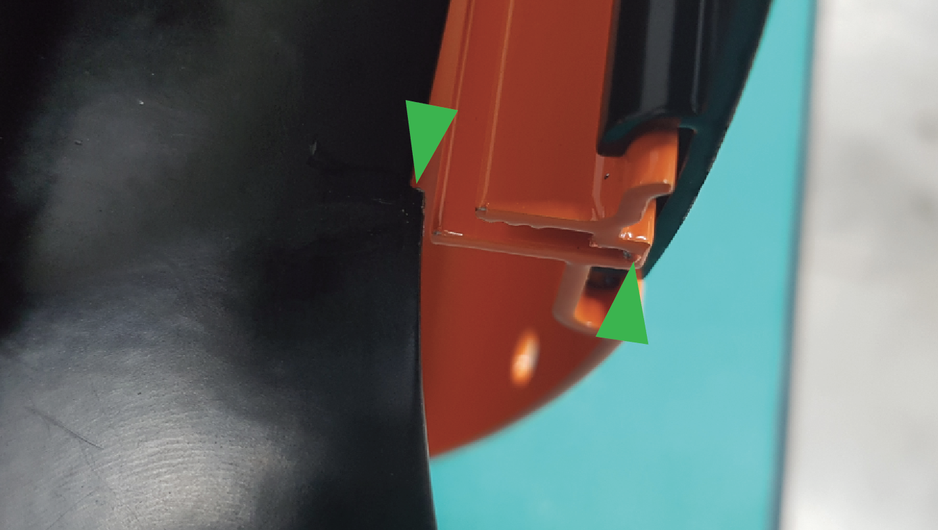
When returning the Extrusions, ensure that the end of the extrusion sits inside the small step in the sheet metal.
Reattach the Corner to the Housing using the Rubber Foot.
Using a 4mm Hex tool, return the two large Bolts to the top of the Corner.
Re-adhere the lifted felt strip.
Reattach all connectors to the PCB.
Did the little wedge fall out? Once everything is reassembled, place the edge on the black sheet metal near where the wedge came from and slide it under the orange extrusion until it cant go any further.
If you encounter any difficulties or have any suggestions for this guide please contact us at info@darkly.com
