
Tools Needed:
- Hex 2.5mm tool
- Mascara brush or small stiff bristled brush
- Microfibre cloth or Lens Wipes
Cleaning Frequency:
Maintaining a clean Laser Unit is crucial for cooling as it ensures efficient heat dissipation, preventing the Laser Module from overheating which will drastically degrade performance and lifespan of the Laser Diodes.
The Lens Cap should be checked and cleaned weekly or after a big cutting job.
The Fan on the Laser Unit should be replaced every 6-12 months or as required.
The frequency of cleaning will vary based on the usage of the machine. Frequencies listed are intended as a guide only and should be increased/decrease as required.
Note: Compressed air can be used during cleaning. However, the Fan is not rated to spin at high speeds – it is recommended that a small amount of pressure be applied to the Fan hub to prevent or limit rotation. Care should also be take not to force dust into the optics area at the bottom of the Laser Unit.
Major Clean:
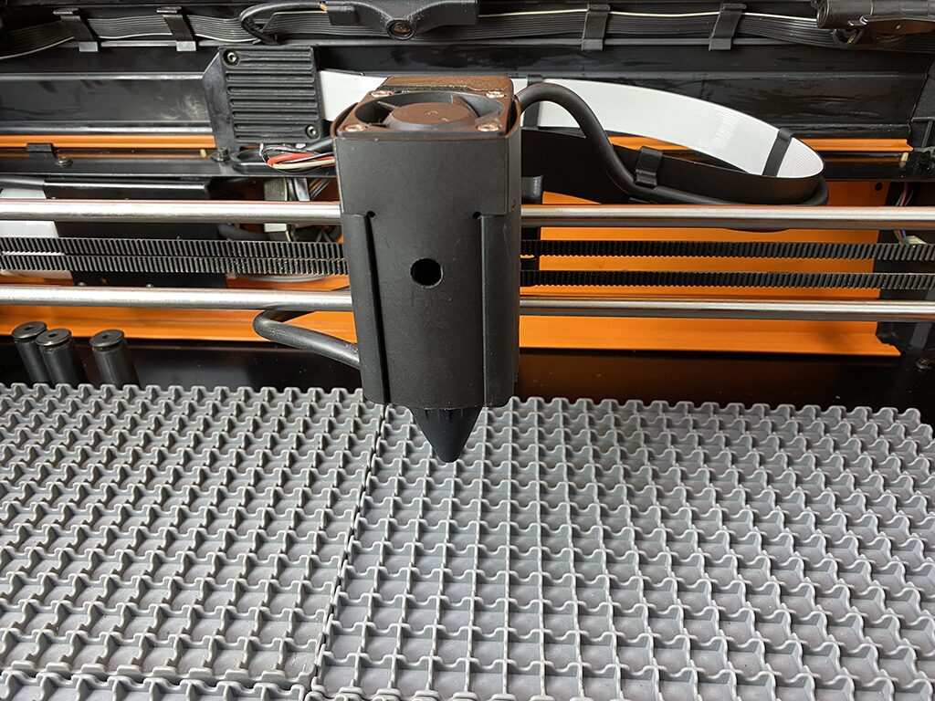
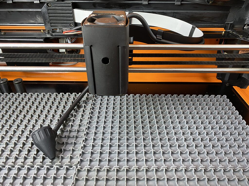
Step 1: With the Emblaser OFF and disconnected, unclip the silicone nozzle.
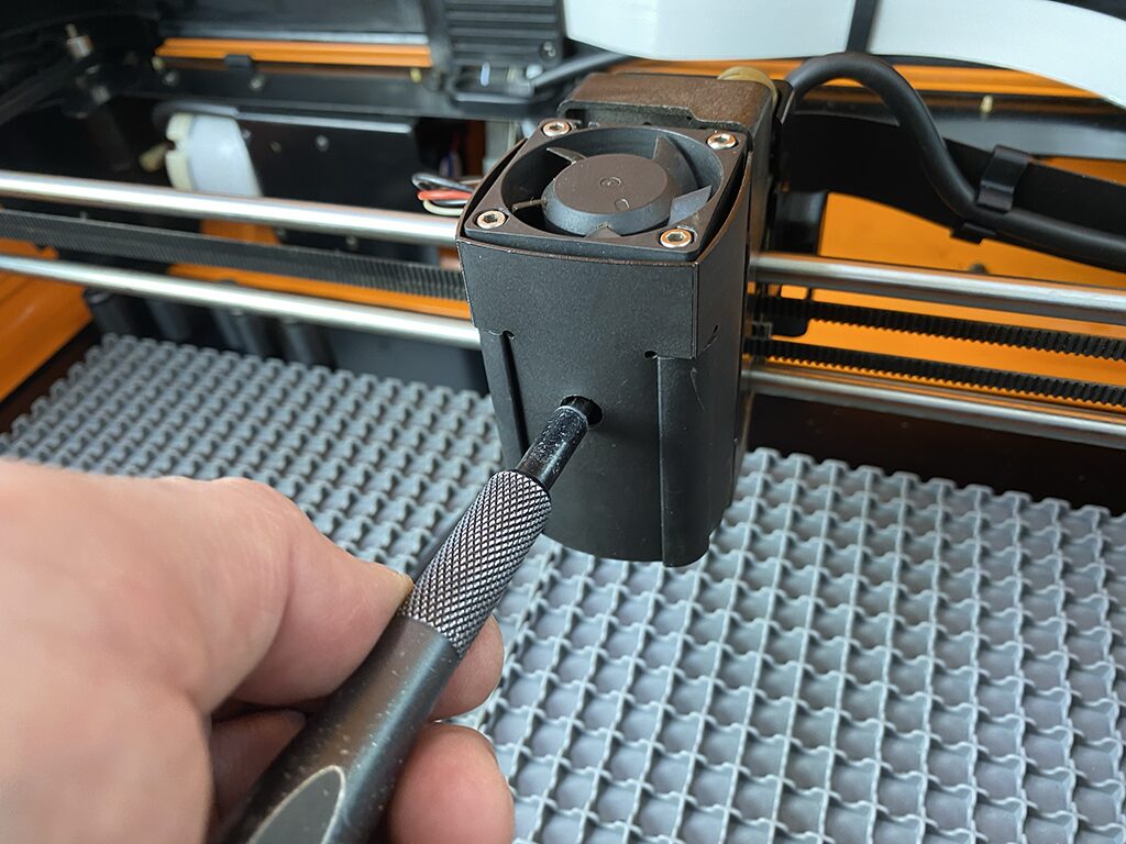
Step 2: Use a 2.5mm Hex tool to detach the laser module. Be careful when handling the module as it will still be plugged in.
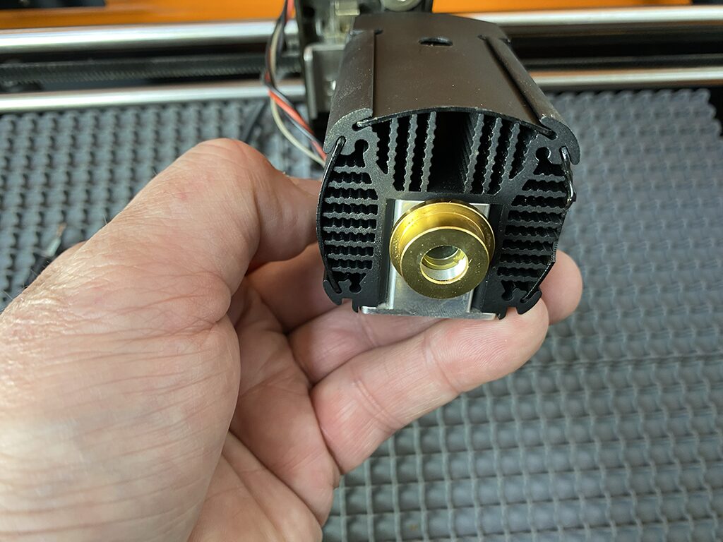
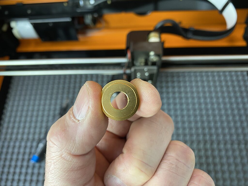
Step 3: Unscrew the Lens cap and clean it with a microfibre cloth of lens wipes. If the glass has marks which cannot be removed, you will need to replace the cap. Replacements are available on our store here: LINK
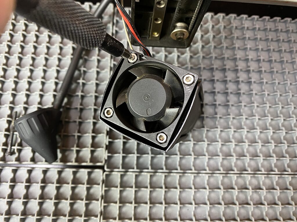
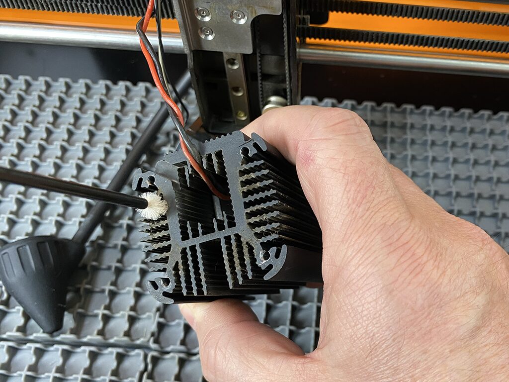
Step 4: Detach the fan from the top of the module by unscrewing the 4 screws using the hex 2.5mm tool.
You can then carefully clean the fins with a fine brush.
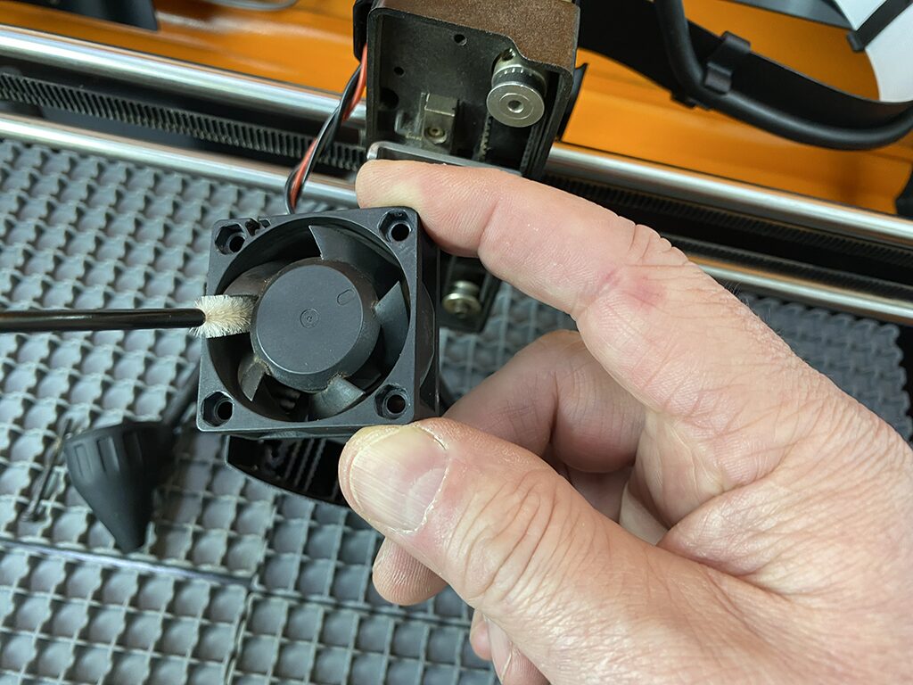
Important: The fan should be replaced every 6-12 months or if it shows any signs of reduced performance. Replacement fans can be ordered from our store here: LINK
Step 5: Slide off the plastic fan shroud. This can then be wiped clean to remove debris build up.
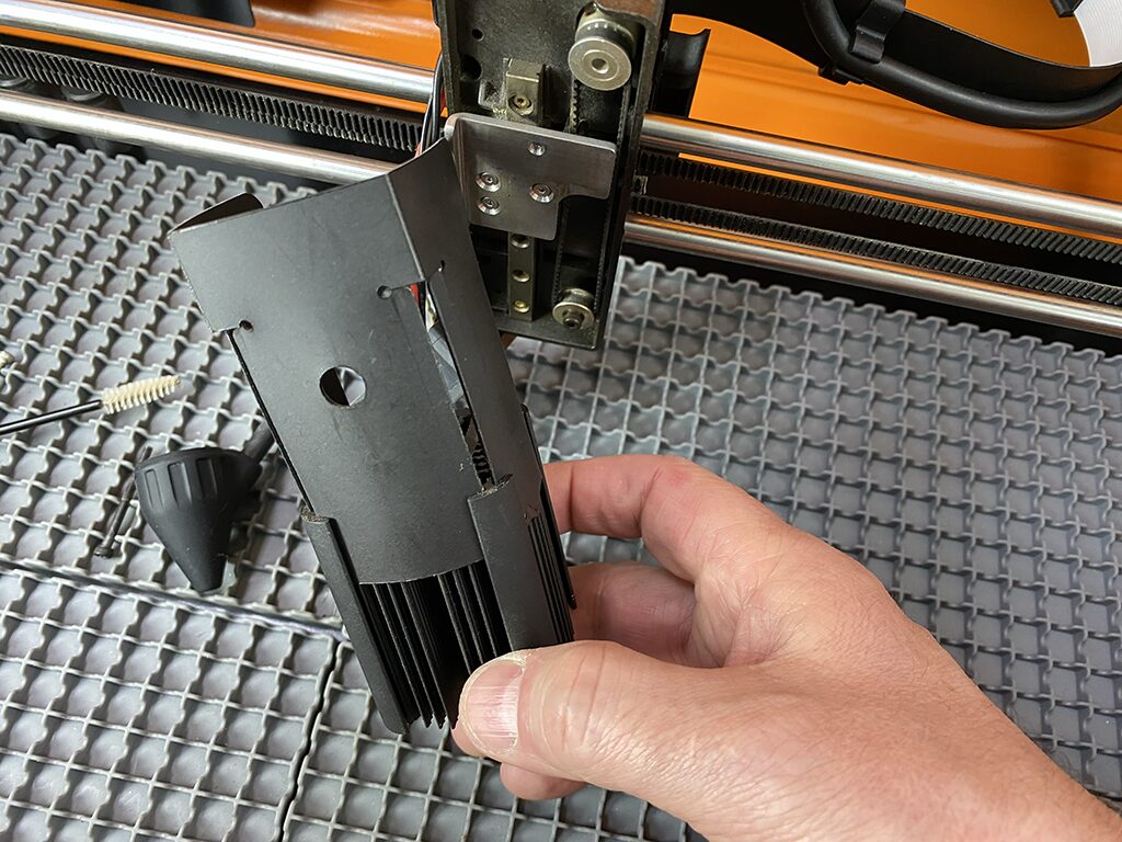
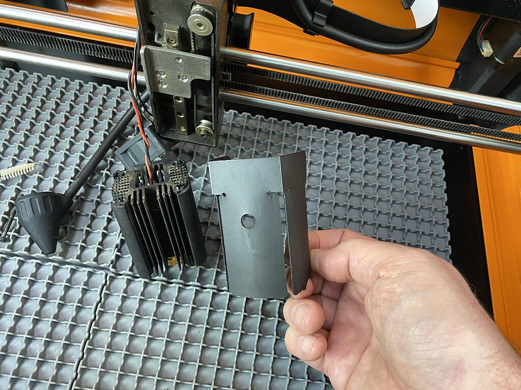
Step 6: With the shroud removed, clean any debris from the cooling fins.
Step 7: Reassemble and you’re Done!

