Replacement Laser Driver PCBs can be bought on the Darkly Labs store here.
Step 1:
Using a fine Philips Head screw driver, remove the two screws holding the cover in place.
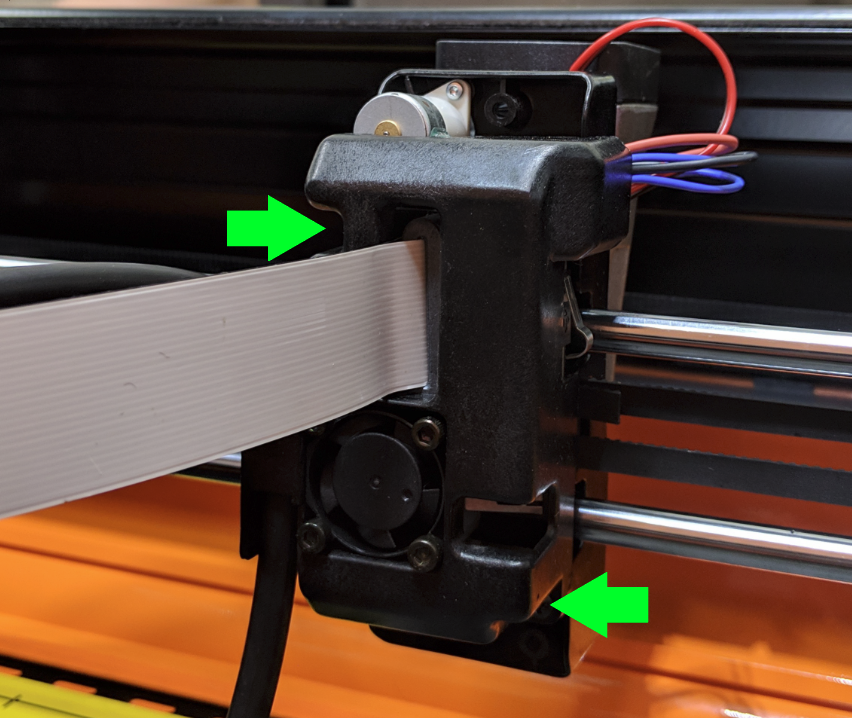
Step 2:
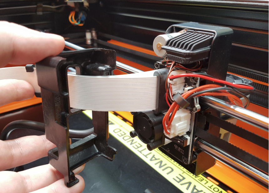
Carefully pull the cover away, pull it along the FFC Strip get get it clear of the Laser Carriage.
Take note of where cables are sitting, this will help when reassembling the cover.
Step 3:
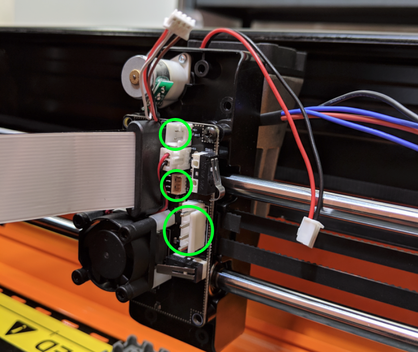
Carefully withdraw the indicated connectors from the Laser Driver PCB. Where possible avoid pulling on the cables.
Step 4:
Remove the two screws holding the Laser Driver PCB to the Laser Carriage.
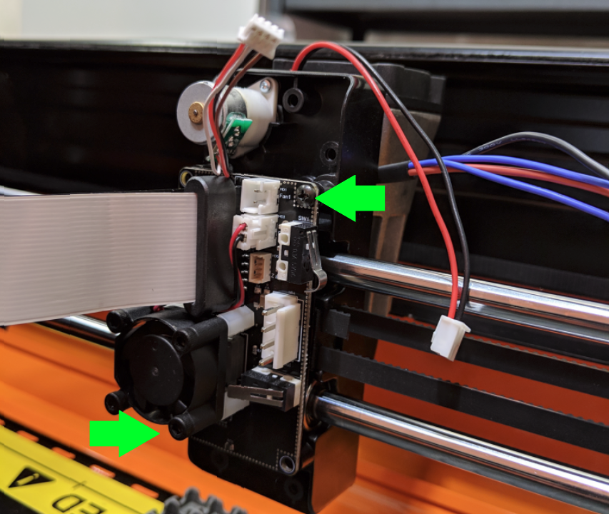
Step 5:
Keep the black insulating layer behind the PCB.
Important: Reattach this layer when assembling your replacement PCB to the laser carriage, failure to do so will damage your device.
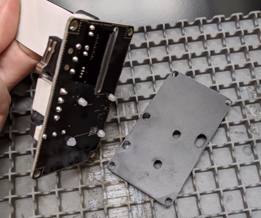
Step 6:
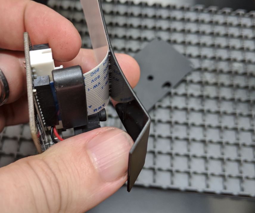
Remove the Support Strip from the back of the PCB.
In newer devices the Support Strip will be black and adhered to the FFC, you may need to peel the FFC back three or four centimetres. Take care to be gentle and even when peeling the FFC off the Support Strip.
Step 7:
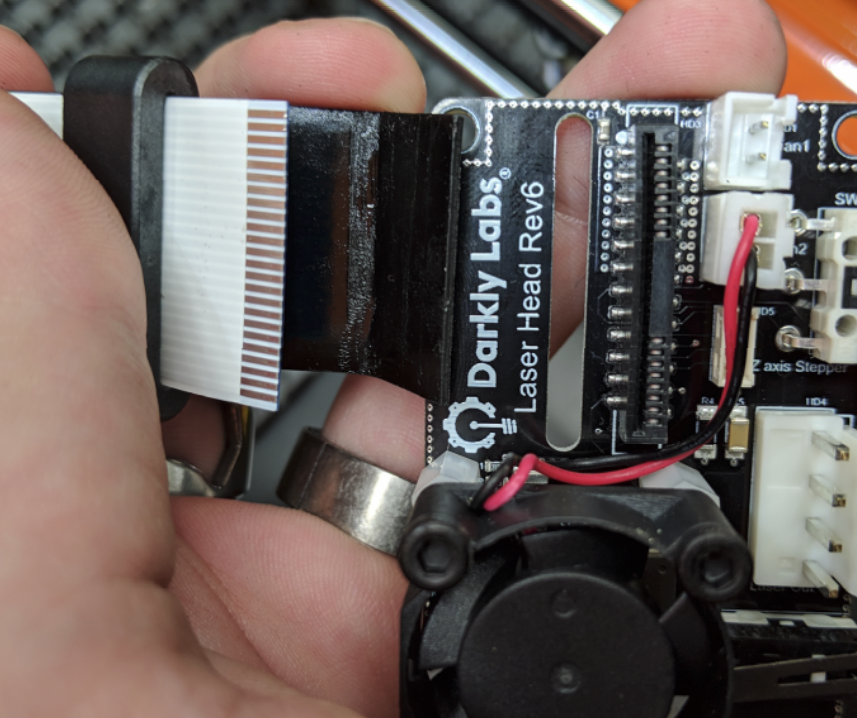
Remove the FFC from its connector.
The connector is delicate, it is important to be gentle when removing the FFC and avoid rocking it side to side. Do you best to keep it square and apply even pressure when withdrawing.
Step 8:
Time to reassemble.
- Connect FFC to replacement PCB
- Position Support Strip through slot in PCB
- Place Insulation over the back of replacement PCB (Earlier machines may have different style of insulation, see images below)
- Attach PCB to Laser Carriage (Keeping insulation in place)
- Reattach connectors to PCB
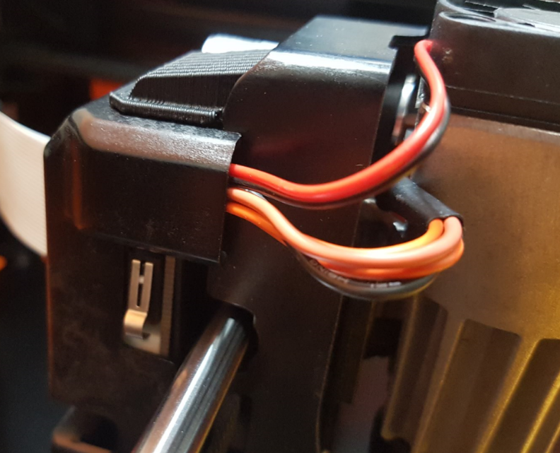
- Reattach PCB Cover (route cables as shown in image below)
Earlier devices may have an insulation layer with an upturned flap like the one shown below.
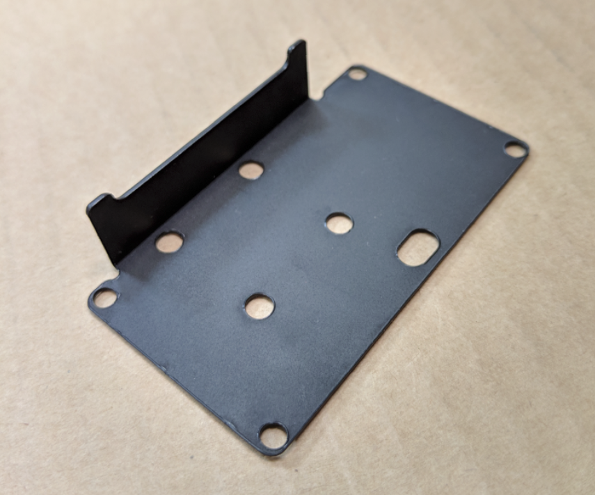
When reassembling tuck this flap under the cover. Leaving the flap loose may cause problems with the operation of your device.
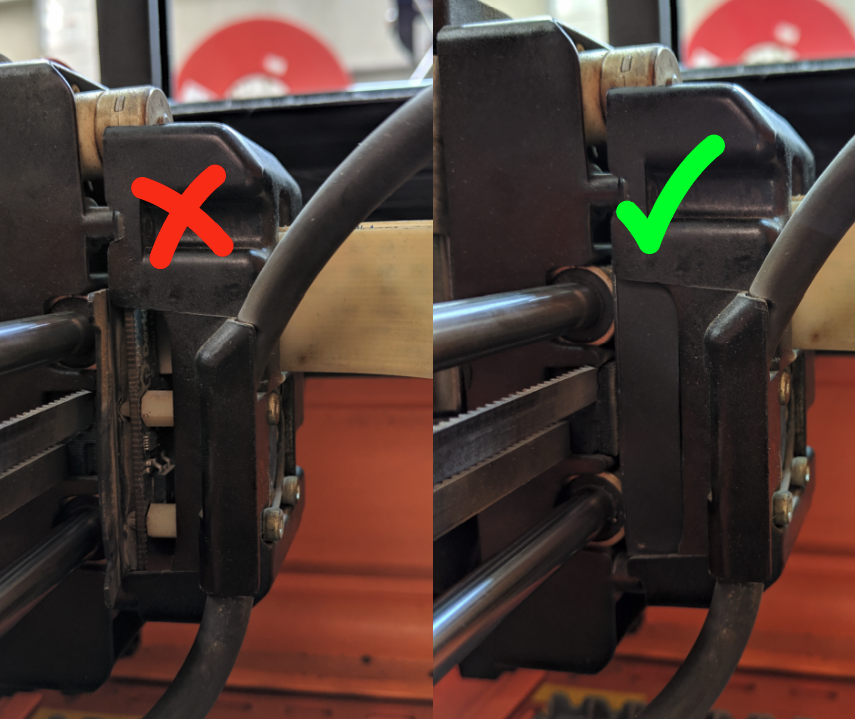
When reattaching the cover, ensure cables are not being pinched and are routed to allow free movement with the Laser Unit.
